Mathey Dearman CNC Saddle Machine User Manual
Page 104
CNC Saddle Machine Parts & Operating Manual 03-0117-MSA 03-0117-1SA 03-0117-2SA
Ver 1.0
104
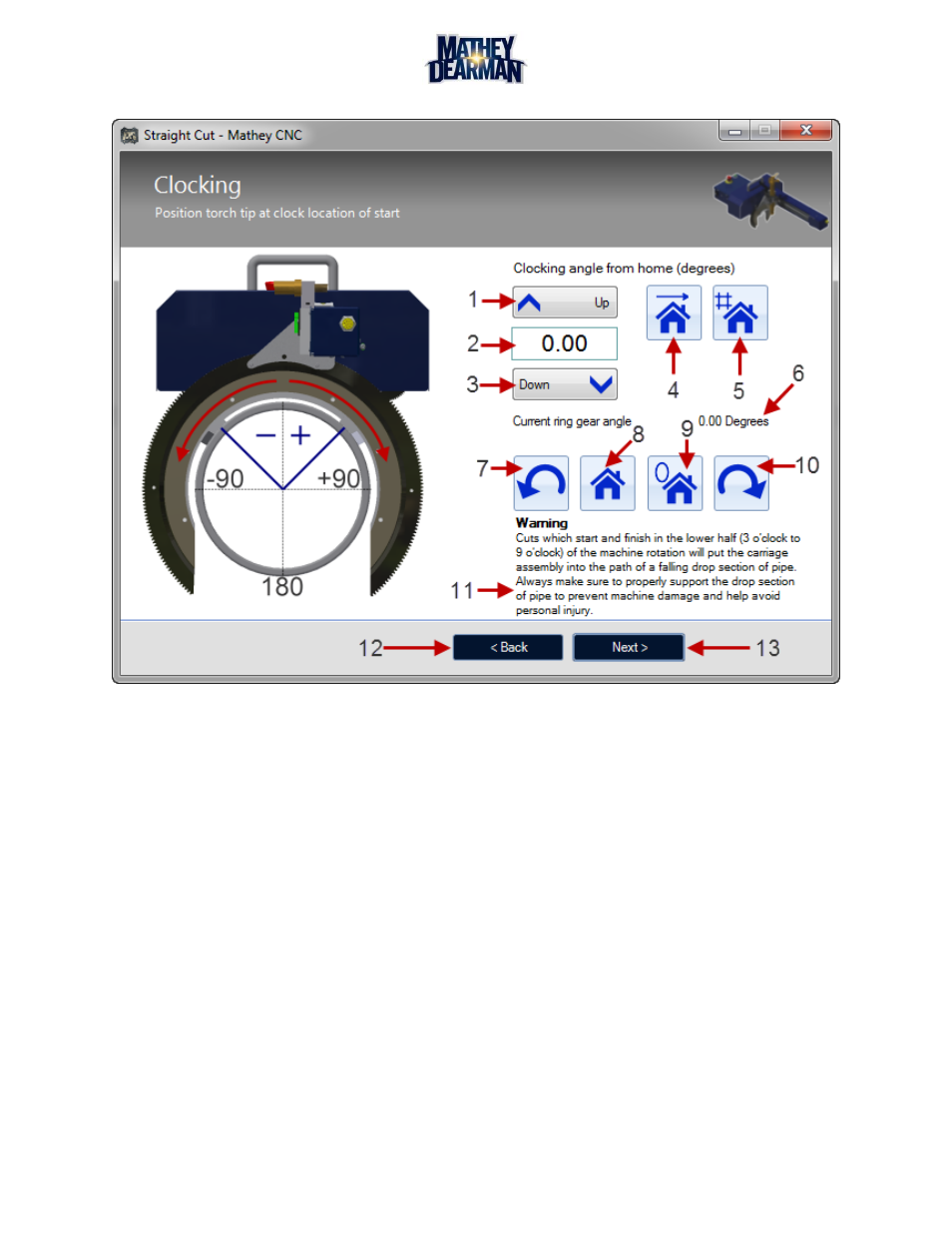
6.7.20 Clocking (Figure 6-63)
Figure 6-63 Clocking Screen
1. Clocking Up Button – Increases the clocking angle by 1 degree. Maximum value is limited by an internal
value (270 degrees).
2. Clocking Angle Value – Angle to rotate the cut path about the z axis of the pipe. All cuts can clocked or
rotated around the pipe by specifying the amount of rotation in degrees.
3. Clocking Down Button – Decreases the clocking angle by 1 degree. Minimum value is limited by an
internal value (-270 degrees).
4. Go To Angle Button – Clicking this button will cause the machine to rotate to the position indicated in
the ‘clocking angle value’ (2) box.
5. Set Clocking From Rotation Button – If possible clicking this button will set the ‘clocking angle value’
box to be whatever the current ring gear angle is. This is useful whenever it is desired to set the starting
position to a clocking value that is physically designated.
6. Current Ring Gear Angle – This label displays what the current ‘defined’ angle of the machine is. The
zero point is defined during the calibration process but can be changed to the current location using the
set home button (9).
7. Jog Counter Clockwise Button – Pressing this button will cause the machine to rotate in the counter
clockwise direction in relation to the front of the machine. This direction is also in the negative domain of
the clocking angle.
8. Go Home Button – This button will move the machine to the defined home zero point of the ring gear or
zero degrees.