Mathey Dearman CNC Saddle Machine User Manual
Page 87
CNC Saddle Machine Parts & Operating Manual 03-0117-MSA 03-0117-1SA 03-0117-2SA
Ver 1.0
87
6.7.3
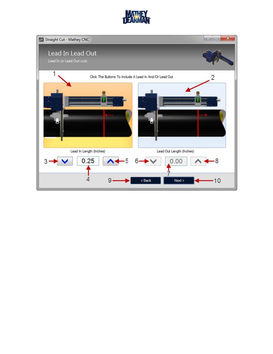
Lead In or Lead Out (Figure 6-46)
Figure 6-46 Lead In or Lead Out Screen
1. Lead In Toggle – Click this icon to include a lead in to the cut path. Clicking the icon changes its color to
orange. Including a lead in allows the pierce point and start of the cut to occur a selected distance off of
the cut path. The length of this lead in (if included) will be the value defined in the box above (4). The
direction of this lead in is defined by the work and drop settings for the cut (6.7.18). By default it is in the
positive Z direction.
2. Lead Out Toggle – Click this icon to include a lead out from the cut path. Clicking the icon changes its
color to orange. Including a lead out instructs the machine to move the torch away from the cut path a
selected distance after the cut is complete. The length of this lead out (if included) will be the value
defined in the box above (7). The direction of this lead out is defined by the work and drop settings of the
cut (6.7.18). By default it is in the positive Z direction.
3. Lead In Down Button – Decrease the length of the lead in by one increment
4. Lead In Value – Length of the lead in (in the z direction) in inches. The lead in length is limited by an
internal minimum of 0.10 inches and a maximum of 2.00 inches.
5. Lead In Up Button – Increase the length of the lead in by one increment.
6. Lead Out Down Button – Decrease the length of the lead out by one increment.
7. Lead Out Value – Length of the lead out (in the z direction) in inches. The lead out length is limited by an
internal minimum of 0.10 inches and a maximum of 2.00 inches.
8. Lead Out Up Button – Increase the length of the lead out by one increment.
9. Back Button – Go to the previous cut selection screen.
10. Next Button – Go to the next cut selection screen.