Mathey Dearman CNC Saddle Machine User Manual
Page 29
CNC Saddle Machine Parts & Operating Manual 03-0117-MSA 03-0117-1SA 03-0117-2SA
Ver 1.0
29
5.3.2
Screw the right hand swivel studs (Figure 5-9, Item 8) into the threaded holes at the 3:00 and 9:00
O’clock position in the ring gear until the swivel studs are flush with the back side of the ring gear
and the swivel eye is oriented as shown in Figure 5-9.
5.3.3
Place the support bar (Figure 5-7, Item 2) on to the carriage and leadscrew assembly (Figure 5-7,
Item 10) with the slot facing downward and the nearest threaded hole to the left of the slot.
NOTE: It may be necessary to compress the sheet metal in order for the support bar to fit the carriage
and leadscrew assembly correctly.
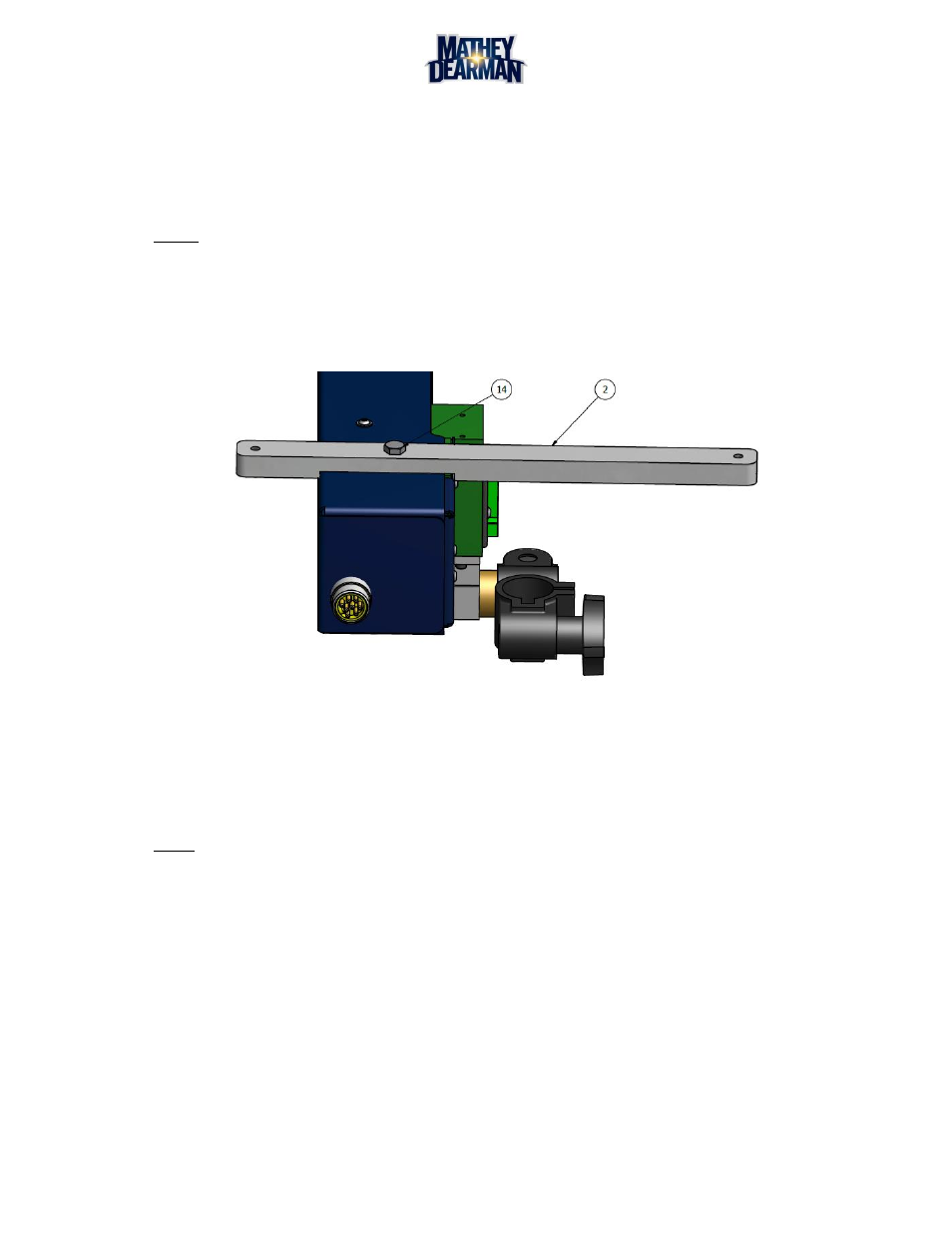
5.3.4
Align the hole in the slot of the support bar (Figure 5-7, Item 2) with the threaded hole in the bottom
of the carriage and leadscrew assembly (Figure 5-7, Item 10) and Insert the 5/16-18 x 3/4 hex head
cap screw (Figure 5-10, Item 14) through the hole in the support bar (Figure 5-10, Item 2) and thread
it into the carriage and leadscrew assembly (Figure 5-7, Item 10) until it is flush with the support bar.
Figure 5-10 Support Bar to Leadscrew Assembly
5.3.5
Place the 5/16-18 x 1” hex head cap screw (Figure 5-9, Item 9) through the right hand swivel stud
located on the right ring gear with the thread facing outward as shown in Figure 5-9.
5.3.6
Place the hole of the swivel stud (Figure 5-9, Item 4) located on support rod (Figure 5-9, Item 12)
over the 5/16-18 x 1” hex head cap screw and install the Hex nut (Figure 5-9, Item 7).
NOTE: Hand tighten all fasteners at this time.
5.3.7
Make sure the hex nut (Figure 5-9, Item 8) on the right hand swivel stud in the ring gear and hex nut
(Figure 5-9, Item 8) on the right hand swivel stud in the support bar are loose.
5.3.8
Place the 5/16-18 x 1” hex head cap screw (Figure 5-11, Item 9) through the right hand swivel stud
(Figure 5-11, Item 6) located in the support bar (Figure 5-7, Item 2) with the thread facing outward
as shown in Figure 5-11.