Mathey Dearman CNC Saddle Machine User Manual
Page 28
CNC Saddle Machine Parts & Operating Manual 03-0117-MSA 03-0117-1SA 03-0117-2SA
Ver 1.0
28
5.2 Carriage and Leadscrew Installation
5.2.1
Remove 3 each of the 5/16-18 hex nuts located on the studs on the ring gear.
5.2.2
Mount the carriage and leadscrew assembly (Figure 5-8 Item 10) to the ring gear (Figure 5-7, Item
11) using the provided 5/16-18 hex nuts (not Shown). First, tighten the (2) outer nuts using the
provided 1/2” wrench. Next finger tighten the center nut, then using the 1/2” wrench, tighten
the center nut 1/4 turn.
NOTE: Over tightening the center nut could cause damage to the carriage and leadscrew assembly.
Figure 5-8 Mounting the Leadscrew Assembly
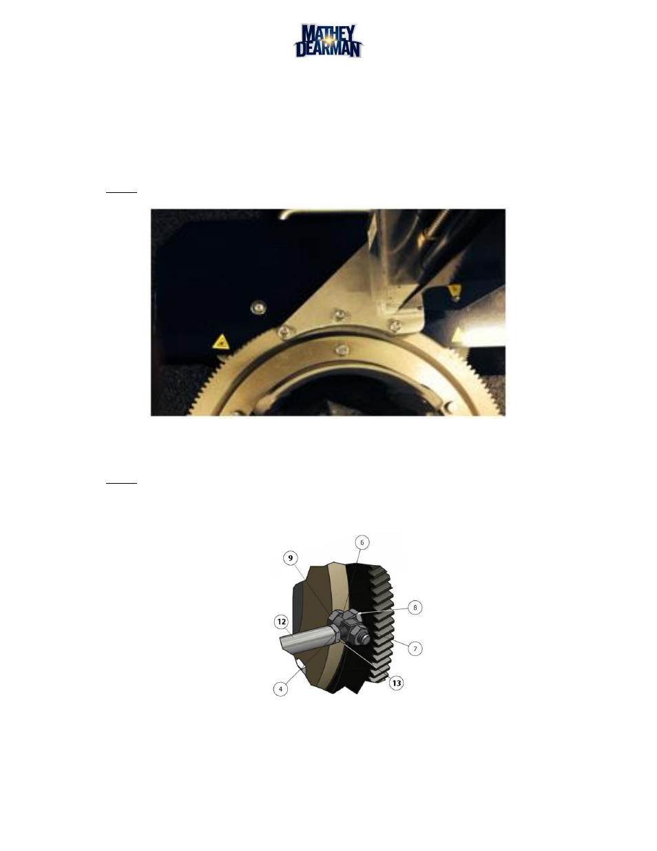
5.3 Support Rod Installation
NOTE: Support Rod length has been pre-set at the factory, however minor adjustment may be required
after field assembly to ensure the most accurate cuts possible.
5.3.1
Screw right hand nuts (Figure 5-9, Item 8) all the way on to right hand swivel studs (Figure 5-9, Item 6).
Figure 5-9 Swivel Stud to Ring Gear Diagram