Mathey Dearman CNC Saddle Machine User Manual
Page 106
CNC Saddle Machine Parts & Operating Manual 03-0117-MSA 03-0117-1SA 03-0117-2SA
Ver 1.0
106
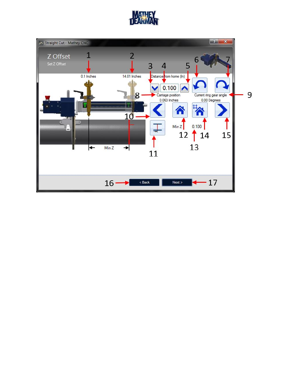
6.7.21 Z-Offset (Straight Cut Only) (Figure 6-64)
Figure 6-64 Z-Offset (Straight Cut Only) Screen
1. Smallest Possible Z-Offset – This value is the smallest allowed z-offset and by default all cuts will have
at least this amount of z-offset.
2. Largest Possible Total Offset – This value is the largest allowed z-offset value, the z-width plus the z
offset cannot be larger than this value. This value is defined during calibration.
3. Z-Offset Down Button – Decrease the value of the z-offset by one decrement. This value is limited by
minimum z offset (1).
4. Z-Offset Value – Value of the z-offset of the cut. The larger this number the further the cut will be away
from the ring gear and the ring gear end of the arm.
5. Z-Offset Up Button – Increase the value of the z-offset by one increment. This value is limited by the
length of the machine and the width of the cut.
6. Jog Counter Clockwise Button – Pressing this button will cause the machine to rotate in the counter
clockwise direction in relation to the front of the machine. The indicator on the screen shows the current
position of the ring gear.
7. Jog Clockwise Button – Pressing this button will cause the machine to rotate in the clockwise direction
in relation to the front of the machine. The indicator on the screen shows the current position of the ring
gear.
8. Current Carriage Position – Shows the current location of the carriage on the leadscrew in inches, it can
be moved by using jog buttons (10 & 15)