Mathey Dearman CNC Saddle Machine User Manual
Page 31
CNC Saddle Machine Parts & Operating Manual 03-0117-MSA 03-0117-1SA 03-0117-2SA
Ver 1.0
31
5.4.3
If using an Oxy/fuel cutting torch, select the correct cutting tip for the material, wall thickness and
fuel gas per the torch manufacturer’s instructions.
5.4.4
Prepare the torch cutting system for operation by following the manufacturer’s instructions
5.4.5
Connect up the laptop and all associated equipment necessary for CNC Saddle Machine operation.
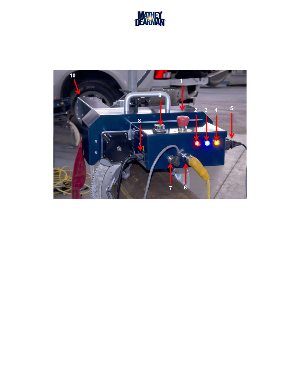
Figure 5-12 CNC Saddle Machine Components and Connections
5.5 Installing Cables
5.5.1
Install the female-threaded end of the yellow 8-Pin Cordset (Figure 2-1, Item 7) into large 8-Pin Panel
Connector (Figure 5-12, Item 6) located on the back of the Machine Control Module (MCM). Hand-
tighten fully.
5.5.2
Install the male-threaded end of the yellow 8-Pin Cordset (Figure 2-1, Item 7) into large 8-Pin Panel
Connector (Figure 5-12, Item 10) located on the end of the Carriage and Leadscrew Assembly. Hand-
tighten fully.
5.5.3
Install USB Cable (Figure 2-1, Item 6) into USB Panel Mount Connector (Figure 5-12, Item 5) located
on the side of the Machine Control Module (MCM). Make sure the white arrows on the connectors
align. Tighten the threaded locking ring securely by hand.
5.5.4
Install the other end of the USB Cable (Figure 2-1, Item 6) into any open USB port on the laptop
computer being used.
5.5.5
Press the red E Stop button (Figure 5-12, Item 1) until an audible click is heard and the button
remains in its lowest fully-depressed position.
5.5.6
Install the female end of the AC Power Cord (Figure 2-1, Item 8) into the AC Connector (Figure 5-12,
Item 8) located on the side of the Machine Control Module (MCM).
5.5.7
Plug the male end of the AC Power Cord (Figure 2-1, Item 8) into a 115 or 230 VAC power source.
For allowable voltages see Table 3-1 CNC Saddle Machine General Specifications .