N 5.4 fo, Figure 5-11 – Mathey Dearman CNC Saddle Machine User Manual
Page 30
CNC Saddle Machine Parts & Operating Manual 03-0117-MSA 03-0117-1SA 03-0117-2SA
Ver 1.0
30
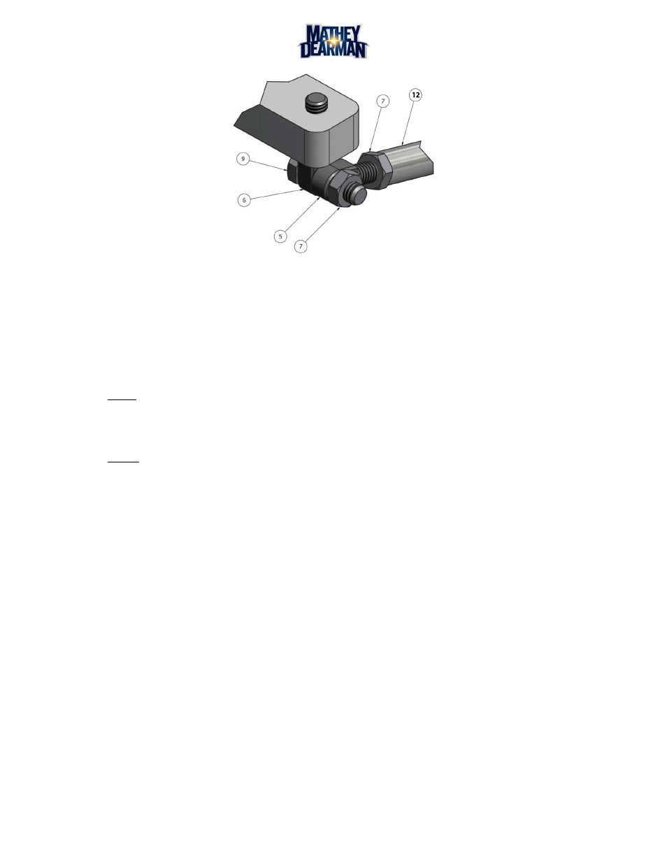
Figure 5-11 Swivel Stud to Support Bar Assembly
5.3.9
Follow the same procedure for the installation of the right hand swivel stud in left side of the ring
gear.
5.3.10 Place the other swivel stud (Figure 5-11, Item 5) located on the other end of the support rod (Figure
5-9, Item 12) over the 5/16-18 x 1” hex head cap screw (Figure 5-11, Item 9) and install the hex nut
(Figure 5-11, Item 7).
NOTE: Hand tighten all fasteners at this time.
5.3.11 Tighten the 5/16-18 x 1” bolt and nut with the provided 1/2” combination wrench allowing the 2
faces of the swivel eyes to come into alignment.
NOTE: The support rods are preset from the factory and should need little to no adjustment.
5.3.12 Tighten hex nut (Figure 5-9, Item 8) on the right hand swivel stud in the ring gear and hex nut
(Figure 5-9, Item 8) on the right hand swivel stud in the support bar (not Shown).
5.3.13 Mount the torch in the torch holder and set the torch tip off the pipe the recommended distance
according to the manufacturer of the torch being used.
5.4 Installing the Cutting Apparatus
5.4.1 Insert a 10” / 254mm long 1 3/8” / 36mm diameter oxy/fuel or plasma arc machine torch (not
supplied) into Rack Adjustable Torch Holder (Fig. 5 Item 17) and adjust torch tip to pipe height per
the torch manufacturer’s instructions. Tighten the Socket Head Cap Screws to secure the torch in the
Torch Holder. A 10” long machine torch is required to allow the 1SA CNC Saddle Machine to cut all
pipe diameters within its range. The Torch Holder is compatible only with a 1 3/8” / 35mm diameter
oxy/fuel or Plasma arc machine torch with a 32-pitch rack. A torch holder to accommodate a metric
torch rack is available separately. It is not necessary to use a machine torch fitted with a rack for
height adjustment. However, if faster torch height adjustment is desired the torch holder is designed
to accept a torch with rack. To increase or decrease the friction of the torch in the Torch Holder,
tighten the Allen Head Cap Screws with a 5/32” Allen wrench.
5.4.2
After the fuel or plasma arc torch is installed and before executing a cut, jog the torch fully around the
pipe to ensure the torch tip to pipe surface distance remains within the torch manufacturer’s
specifications. To obtain proper torch height when cutting the smallest pipe diameter in the
machine’s range, it may be necessary to relocate the torch bracket (03-0116-082) to the bottom side
of the torch carriage assembly by removing the two (2) Allen Head Cap Screws and reinstalling the
bracket on the underside of the torch carriage.