Mathey Dearman CNC Saddle Machine User Manual
Page 34
CNC Saddle Machine Parts & Operating Manual 03-0117-MSA 03-0117-1SA 03-0117-2SA
Ver 1.0
34
5.6.4
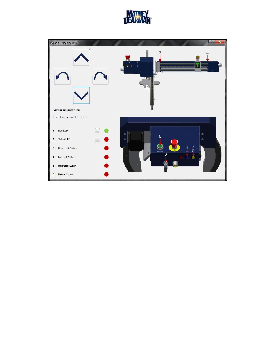
Select the Jog/machine info screen. (See Figure 5-15)
Figure 5-15 Jog/Machine Info Screen
NOTE: The Jog/Machine Info Screen is also a diagnostic screen indicating key components are
functioning properly.
5.6.5
Use the arrows at top left to rotate and move the torch tip along the surface of the pipe.
5.6.6
Observe the torch tip to pipe distance at the home position (3) and the end position (4) locations.
The distance should be equal. If so then go to 5.6.9.
5.6.7
Loosen both hex nuts (Figure 5-9, Item 13 & Figure 5-11, Item 7) at the ends of the support rod
(Figure 5-9, Item 12)
NOTE: Exercise caution as one end will have a right hand nut and the other end will have a left hand
nut. The end of the support rod that has a left hand nut will be marked with an “L”.
5.6.8
Adjust both support rods evenly until the cutting tip to pipe distance is the same at the home position
(3) and end position (4) of torch arm travel.
5.6.9
Rotate the Ring Gear in both directions into the Saddle and Cap Ring assembly. The Ring Gear should
move into the Saddle and Cap Ring assembly without deviation or interruption.
5.6.10 If necessary, adjust the support rods so that the Ring Gear enters the Saddle and Cap Ring cavity
properly.
5.6.11 If no adjustment is necessary, tighten both hex nuts (Figure 5-9, Item 13 & Figure 5-11, Item 7) at the
ends of the support rods (Figure 5-9, Item 12).