E figure – Mathey Dearman CNC Saddle Machine User Manual
Page 26
CNC Saddle Machine Parts & Operating Manual 03-0117-MSA 03-0117-1SA 03-0117-2SA
Ver 1.0
26
5.1.4.3
In order to get a stable installation of the Saddle Machine, the Chain (Figure 5-4, Item 3) of the
Boomer Assembly must be adjusted on the Spring Snap (Figure 5-4, Item 4) so that the spring is
stretched approximately 1/2" -3/4” (12 - 19mm) when the Boomer is closed.
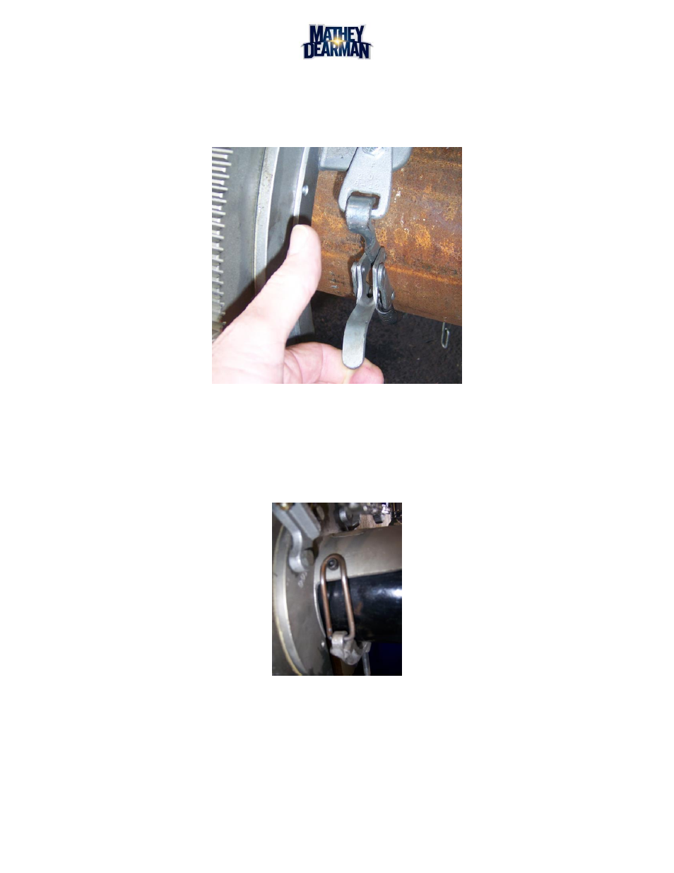
5.1.4.4
When the Chain is properly adjusted, close the Boomer. (See Figure 5-5)
Figure 5-5 1SA / 2SA Spring Boomer Latch Installation
5.1.5
Boomer Assembly Installation (MSA Only)
5.1.5.1
Place the Eye of the Boomer Assembly over ¼-20 x ¾” Socket Head Cap Screw located on the
Saddle. (See Figure 5-6)
5.1.5.2
Tighten the Thumb Screw of the Boomer Assembly to secure the machine to the pipe.
Figure 5-6 MSA Boomer Assembly Installation