Mathey Dearman CNC Saddle Machine User Manual
Page 25
CNC Saddle Machine Parts & Operating Manual 03-0117-MSA 03-0117-1SA 03-0117-2SA
Ver 1.0
25
5.1.2.3
Secure Spacer Bolts to the Saddle by threading Hex Nut onto the threaded portion on the topside of
Saddle. The hex nut does not have to be tightened with a wrench as the purpose of the nut is to
secure the spacer bolt to the Saddle.
5.1.3
Spacer Bolt Installation (MSA Only)
5.1.3.1
Select the correct spacer for pipe being cut. The Saddle is placed on the pipe without spacers for
cutting 4”/101.6mm pipe.
5.1.3.2
Place the spacer on the inside the front Saddle and align the threaded hole in the spacer with the
hole in the front of the Saddle.
Figure 5-3 MSA Spacer Bolt Installation
5.1.3.3
Secure Spacer to the Saddle by placing 1/4-20 X 5/8” machine screw through the hole in the top
side of the Saddle and threading it into the Spacer. The machine screw does not have to be
tightened with a wrench as the purpose of the nut is to secure the spacer bolt to the Saddle.
5.1.4
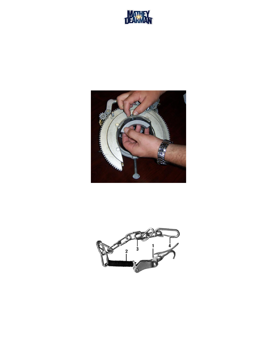
Boomer Assembly Installation (1SA / 2SA Only)
Figure 5-4 1SA / 2SA Spring Boomer Latch Assembly
5.1.4.1
Place the hook of the Boomer (Figure 5-4, Item 1) into the Boomer Eye on the Saddle. (See Figure
5.1.4.2
Place the Spring Snap (Figure 5-4 Item 4) into the Boomer Eye on the other side of the Saddle
(Figure 5 Item 1).