Mathey Dearman CNC Saddle Machine User Manual
Page 19
CNC Saddle Machine Parts & Operating Manual 03-0117-MSA 03-0117-1SA 03-0117-2SA
Ver 1.0
19
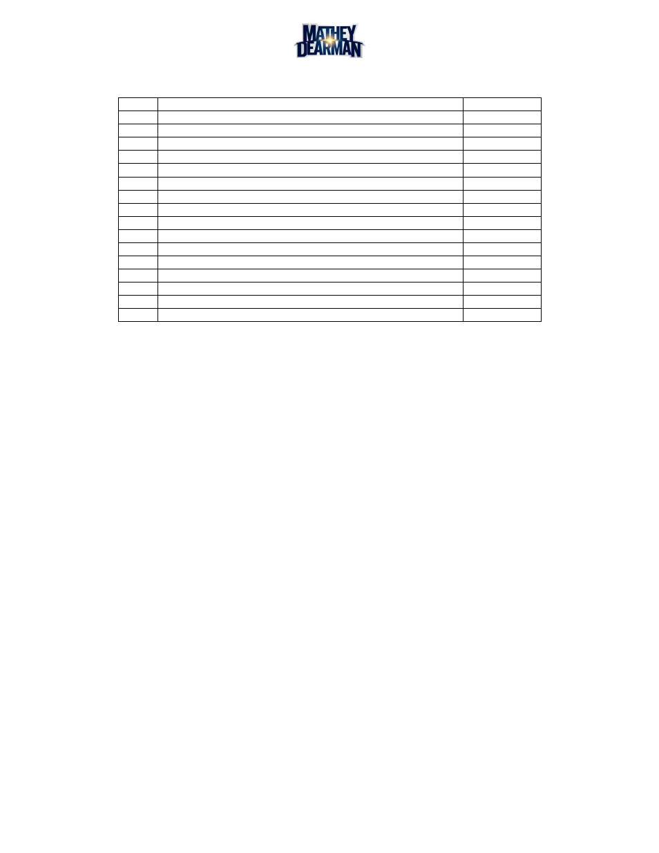
Table 4-3 2SA Saddle Machine Component Assembly Parts Identification
Item
Description
Part Number
1
Hex Head Cap Screw 1/4"-20, 1g.
10-14C0-100
2
Washer, ¼” Flat
12-0014-F00
3
Standoff Bracket – 2SA
03-0117-025
4
Handle, Round-Grip Pull
03-0117-020
5
Hex Head Cap Screw, 3/8-16 x 1” lg.
10-38C0-100
6
Hex Nut, 3/8-16
1H-38C0-000
7
2SA Saddle Machine
03-0117-057
8
Bracket, Motor Back – 2SA
03-0117-031
9
Cover Standoff – 2SA
03-0117-042
10
Standoff, Rear - 1SA/2SA
03-0117-027
11
K-Coupling
03-0204-001
12
NEMA 34 Stepper Motor
01-0249-064
13
Cover, Ring Gear – 2SA
03-0117-023
14
Button Head Cap Screw, 1/4-20 x 1/2” lg.
26-14C0-012
15
Button Head Cap Screw, 10-24 x 3/4” lg.
26-10C0-034
16
Crush Symbol Decal (not shown)
01-0209-031