RLE FMS8 User Manual
Page 11
Falcon User Guide
11
TB1-1 (+) Input for 24/48VDC power
TB1-2 (-) Input for 24/48VDC power
P1 24VDC wall adapter input (center +)
(not available with 48VDC version)
TB2-1 24VDC positive (+)
(power for sensors)
TB2-2 24VDC positive (+)
(power for sensors)
TB2-3 Channel 1 positive (+)
TB2-4 Channel 1 negative (-)
TB2-5 Channel 2 positive (+)
TB2-6 Channel 2 negative (-)
TB2-7 Channel 3 positive (+)
TB2-8 Channel 3 negative (-)
TB2-9 Channel 4 positive (+)
TB2-10 Channel 4 negative (-)
TB3-1 Channel 5 positive (+)
TB3-2 Channel 5 negative (-)
TB3-3 Channel 6 positive (+)
TB3-4 Channel 6 negative (-)
TB3-5 Channel 7 positive (+)
TB3-6 Channel 7 negative (-)
TB3-7 Channel 8 positive (+)
TB3-8 Channel 8 negative (-)
TB3-9 24VDC ground (power for sensors)
TB3-10 24VDC ground (power for sensors)
TB4-1 Relay 1 normally closed (NC)
TB4-2 Relay 1 normally open (NO)
TB4-3 Relay 1 common
TB4-4 Relay 2 normally closed (NC)
TB4-5 Relay 2 normally open (NO)
TB4-6 Relay 2 common
TB5-1 Keypad column 1
TB5-2 Keypad column 2
TB5-3 Keypad column 3
TB5-4 Keypad row 1
TB5-5 Keypad row 2
TB5-6 Keypad row 3
TB5-7 Keypad row 4
TB5-8 Unused
TB5-9 Input signal normally open (NO)
TB5-10 Input signal return
TB6-1 EIA-485 positive (+)
TB6-2 EIA-485 negative (-)
TB6-3 EIA-485 ground
SW2-1 Unit termination switch
SW2-2 Master/slave switch
P6 EIA-232 female DB9 pin connector
P3 RJ-11 telephone line connector
P4 Ethernet 10BaseT connector
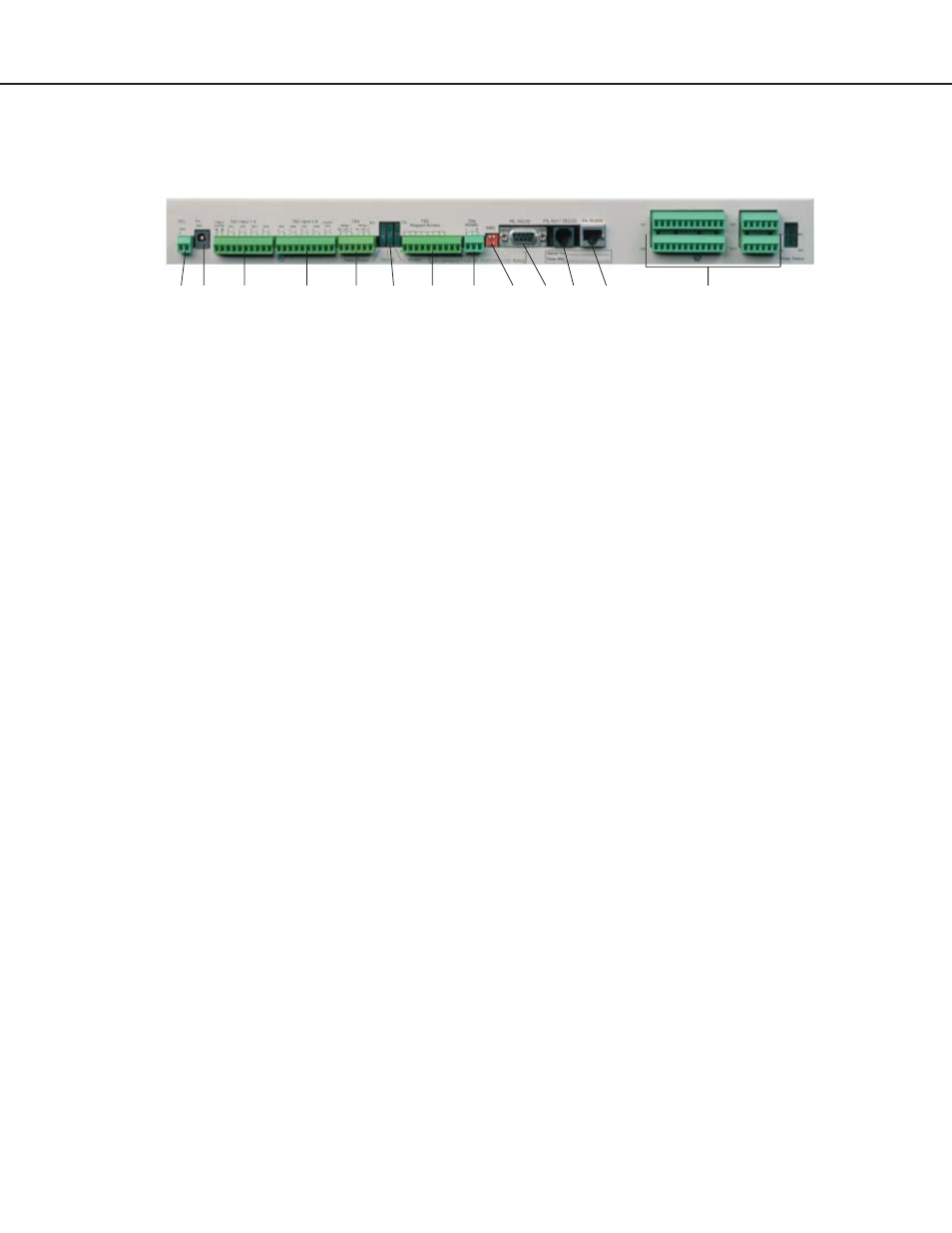
Falcon Terminal Block Designations
TB1 P1 TB2
TB3 TB4
TB5 TB6 SW2 P6 P3 P4
Option Card
Status
LEDs