RLE FMS8 User Manual
Page 12
Falcon User Guide
12
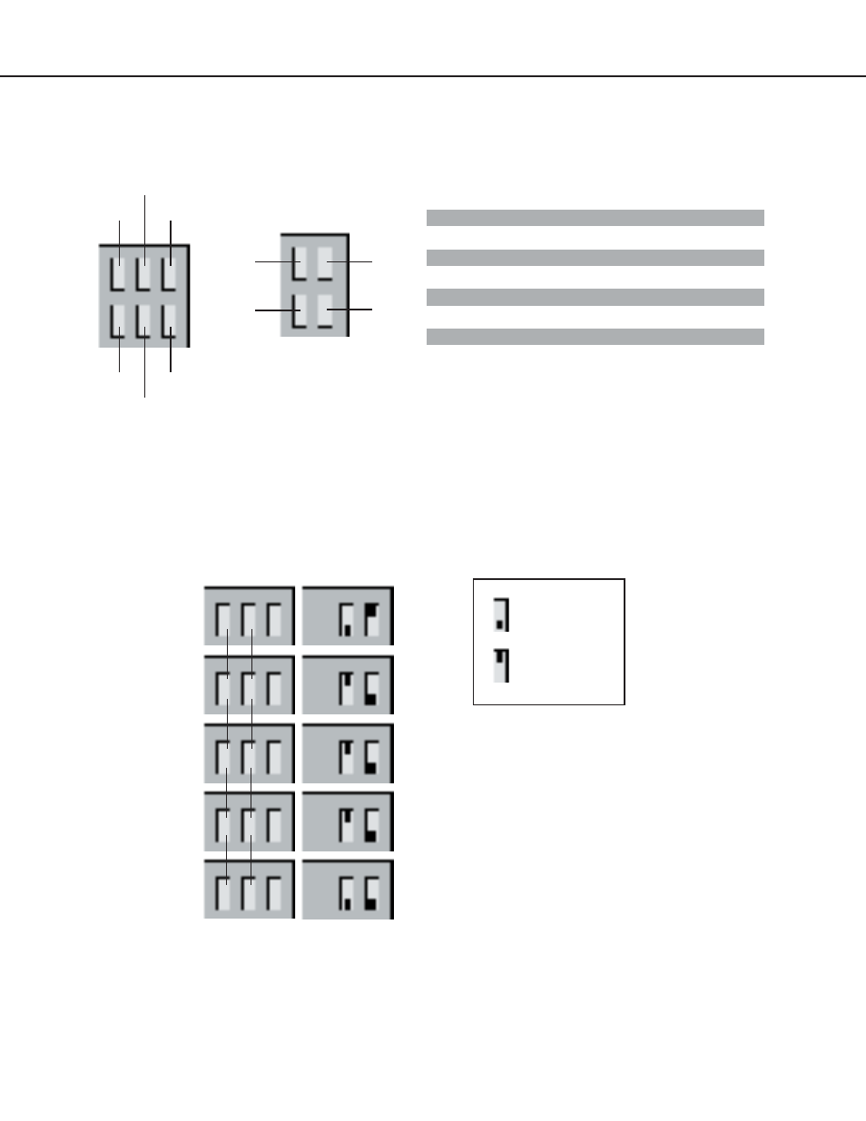
Falcon Rear Panel Indicators - Relay and Communication Status LEDs
The rear panel of the Falcon houses a series of green LEDs. The chart tracks indicator status when the
corresponding green LED is illuminated:
K1
K2
EIA-232 TX
EIA-232 RX
EIA-485 TX
EIA-485 RX
K3
K4
K5
K6
Option Card
Base System
EIA-232 TX interface
Data is being transmitted
Status Indicator
K1 output relay
Energized
K2 output relay
Energized
EIA-232 RX interface
Data is being received
EIA-485 TX interface
Data is being transmitted
EIA-485 RX interface
Data is being received
K3 to K6 output relays
Energized (option card)
+
-
Gnd
+
-
Gnd
+
-
Gnd
+
-
Gnd
+
-
Gnd
Off
On
1
2
Off
On
1
2
Off
On
1
2
Off
On
1
2
Off
On
1
2
Master Unit #1
Slave Unit #2
Slave Unit #3
Slave Unit #4
Slave Unit #5
TB6
EIA-485
SW2
Switch is on.
Switch is off.
SW2-1 Termination switch ON (down) for first and last unit wired in the series.
Termination switch OFF (up) for all units between the first and last units wired in the series.
SW2-2 Master/Slave switch OFF (up) for master unit and ON (down) for slave units.
Detailed Switch Settings