Dlsw operation configuration example, Network requirements, Configuration procedure – H3C Technologies H3C S6300 Series Switches User Manual
Page 168
155
Min SD delay: 0 Min DS delay: 0
Number of SD delay: 4 Number of DS delay: 4
Sum of SD delay: 1390 Sum of DS delay: 1079
Square-Sum of SD delay: 483202 Square-Sum of DS delay: 973651
SD lost packets: 0 DS lost packets: 0
Lost packets for unknown reason: 0
Voice scores:
Max MOS value: 4.38 Min MOS value: 4.38
Max ICPIF value: 0 Min ICPIF value: 0
DLSw operation configuration example
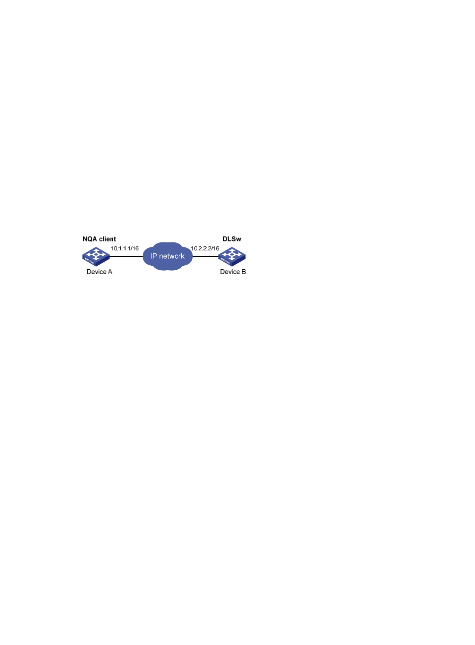
Network requirements
As shown in
, configure a DLSw operation to test the response time of the DLSw device.
Figure 48 Network diagram
Configuration procedure
# Assign each interface an IP address. (Details not shown.)
# Configure static routes or a routing protocol to make sure the devices can reach each other. (Details not
shown.)
# Create a DLSw operation, and configure 10.2.2.2 as the destination IP address.
<DeviceA> system-view
[DeviceA] nqa entry admin test1
[DeviceA-nqa-admin-test1] type dlsw
[DeviceA-nqa-admin-test1-dlsw] destination ip 10.2.2.2
# Enable the saving of history records.
[DeviceA-nqa-admin-test1-dlsw] history-record enable
[DeviceA-nqa-admin-test1-dlsw] quit
# Start the DLSw operation.
[DeviceA] nqa schedule admin test1 start-time now lifetime forever
# After the DLSw operation runs for a period of time, stop the operation.
[DeviceA] undo nqa schedule admin test1
# Display the most recent results of the DLSw operation.
[DeviceA] display nqa result admin test1
NQA entry (admin admin, tag test1) test results:
Send operation times: 1 Receive response times: 1
Min/Max/Average round trip time: 19/19/19
Square-Sum of round trip time: 361
Last succeeded probe time: 2011-11-22 10:40:27.7
Extended results: