Configuration procedure – H3C Technologies H3C S6300 Series Switches User Manual
Page 50
37
•
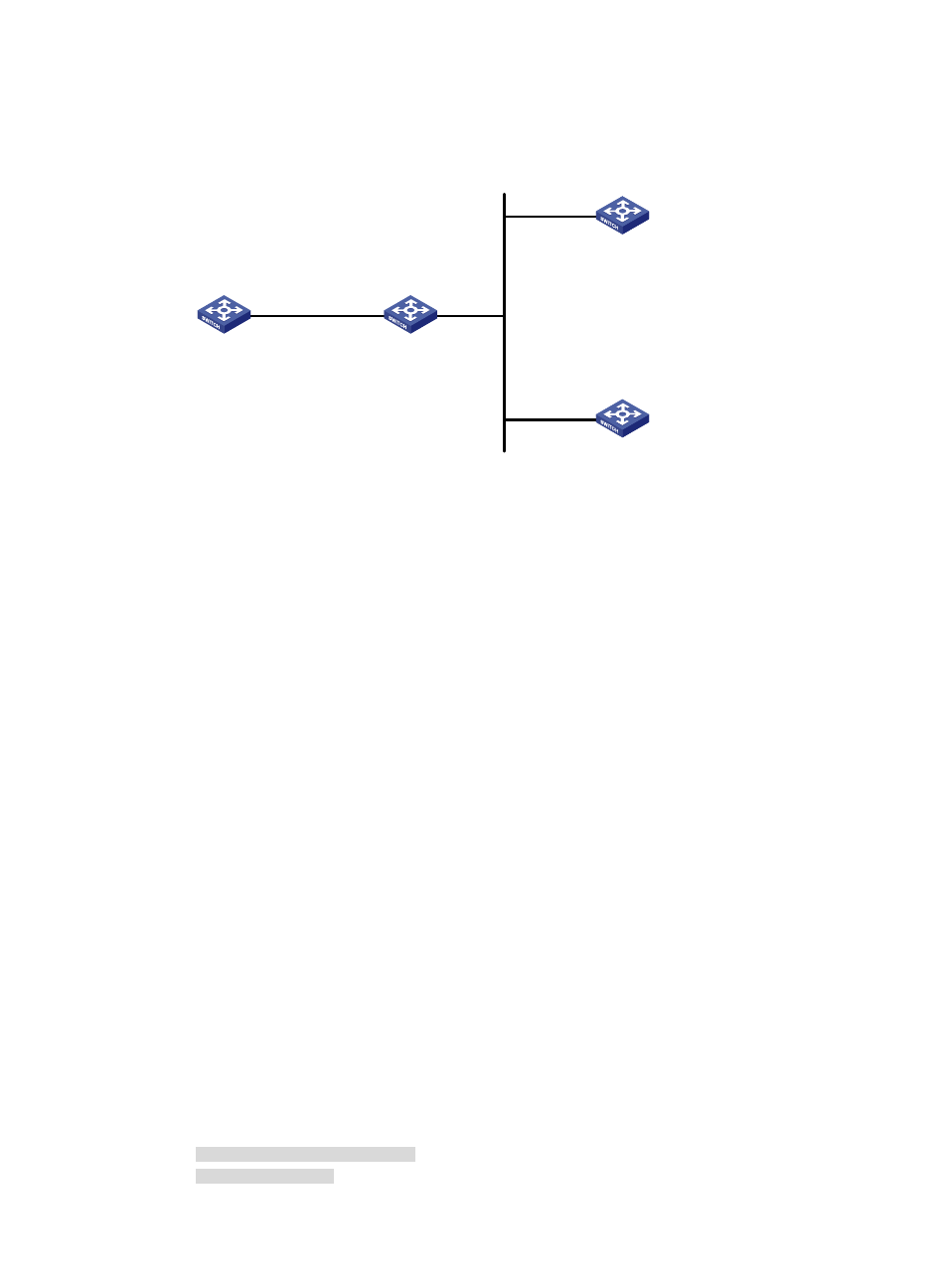
Switch A and Switch D operate in multicast client mode and receive multicast messages through
VLAN-interface 3 and VLAN-interface 2, respectively.
Figure 13 Network diagram
Configuration procedure
In this example, Switch B must support IPv4 multicast routing.
1.
Set the IP address for each interface as shown in
. (Details not shown.)
2.
Configure Switch C:
# Enable the NTP service.
<SwitchC> system-view
[SwitchC] ntp-service enable
# Specify the local clock as the reference source, with the stratum level 2.
[SwitchC] ntp-service refclock-master 2
# Configure Switch C to operate in multicast server mode and send multicast messages through
VLAN-interface 2.
[SwitchC] interface vlan-interface 2
[SwitchC-Vlan-interface2] ntp-service multicast-server
3.
Configure Switch D:
# Enable the NTP service.
<SwitchD> system-view
[SwitchD] ntp-service enable
# Configure Switch D to operate in multicast client mode and receive multicast messages on
VLAN-interface 2.
[SwitchD] interface vlan-interface 2
[SwitchD-Vlan-interface2] ntp-service multicast-client
4.
Verify the configuration:
# Because Switch D and Switch C are on the same subnet, Switch D can receive the multicast
messages from Switch C without being enabled with the multicast functions and can be
synchronized to Switch C. Display the NTP status of Switch D after clock synchronization.
[SwitchD-Vlan-interface2] display ntp-service status
Clock status: synchronized
Clock stratum: 3
Vlan-int3
1.0.1.11/24
Vlan-int3
1.0.1.10/24
Vlan-int2
3.0.1.31/24
Vlan-int2
3.0.1.32/24
Vlan-int2
3.0.1.30/24
Switch A
NTP multicast client
Switch B
Switch C
NTP multicast server
Switch D
NTP multicast client