Configuration procedure – H3C Technologies H3C S6300 Series Switches User Manual
Page 58
45
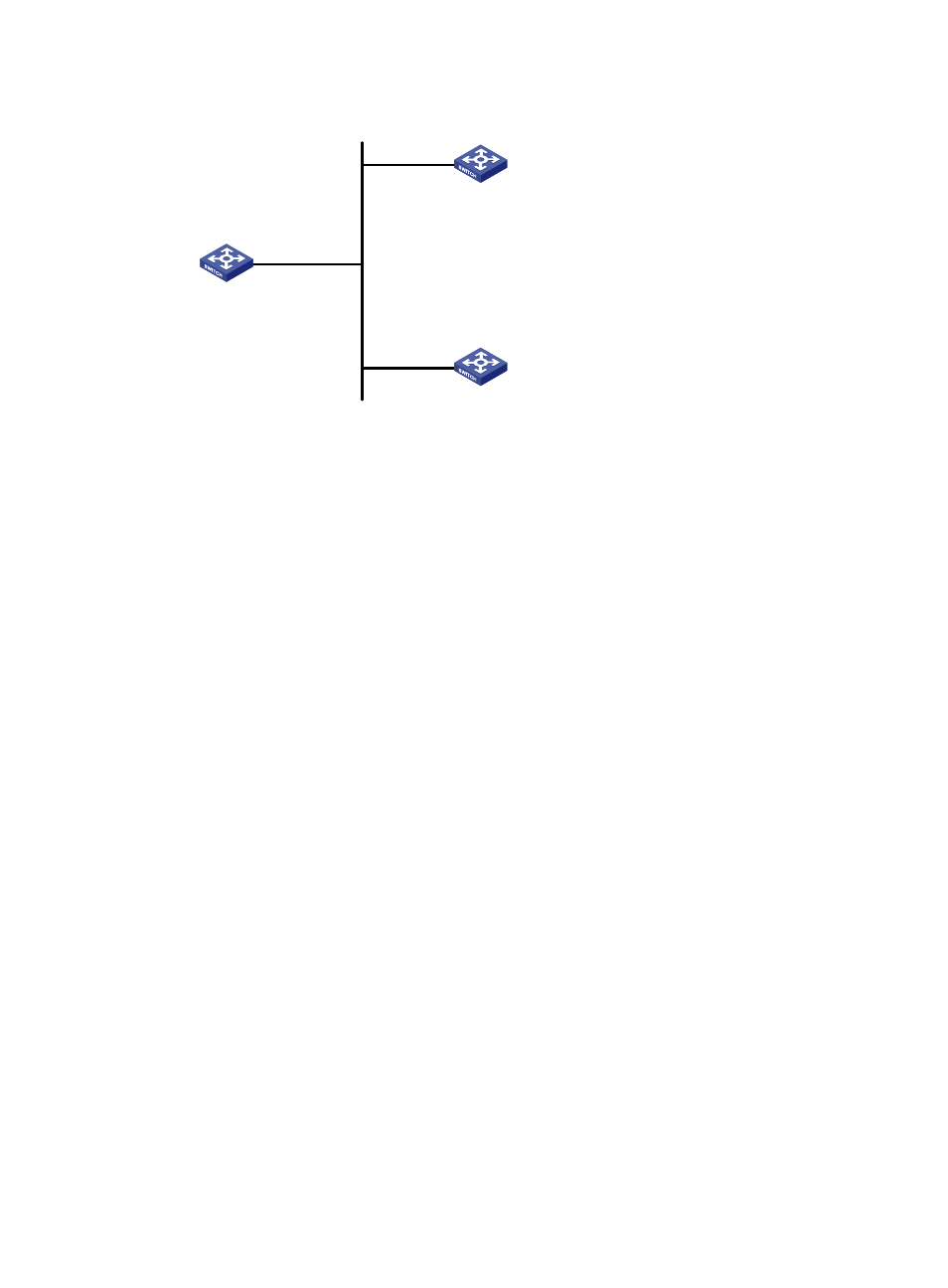
Figure 16 Network diagram
Configuration procedure
1.
Set the IP address for each interface as shown in
. (Details not shown.)
2.
Configure Switch A:
# Enable the NTP service.
<SwitchA> system-view
[SwitchA] ntp-service enable
# Enable NTP authentication on Switch A. Configure an NTP authentication key, with the key ID of
88 and key value of 123456. Input the key in plain text, and specify it as a trusted key.
[SwitchA] ntp-service authentication enable
[SwitchA] ntp-service authentication-keyid 88 authentication-mode md5 simple 123456
[SwitchA] ntp-service reliable authentication-keyid 88
# Configure Switch A to operate in NTP broadcast client mode and receive NTP broadcast
messages on VLAN-interface 2.
[SwitchA] interface vlan-interface 2
[SwitchA-Vlan-interface2] ntp-service broadcast-client
3.
Configure Switch B:
# Enable the NTP service.
<SwitchB> system-view
[SwitchB] ntp-service enable
# Enable NTP authentication on Switch B. Configure an NTP authentication key, with the key ID of
88 and key value of 123456. Input the key in plain text and specify it as a trusted key.
[SwitchB] ntp-service authentication enable
[SwitchB] ntp-service authentication-keyid 88 authentication-mode md5 simple 123456
[SwitchB] ntp-service reliable authentication-keyid 88
# Configure Switch B to operate in broadcast client mode and receive NTP broadcast messages
on VLAN-interface 2.
[SwitchB] interface vlan-interface 2
[SwitchB-Vlan-interface2] ntp-service broadcast-client
4.
Configure Switch C:
# Enable the NTP service.
Vlan-int2
3.0.1.31/24
Vlan-int2
3.0.1.32/24
Vlan-int2
3.0.1.30/24
Switch A
NTP broadcast client
Switch C
NTP broadcast server
Switch B
NTP broadcast client