Ipv6 ntp client/server mode configuration example, Network requirements, Configuration procedure – H3C Technologies H3C S6300 Series Switches User Manual
Page 43
30
IPv6 NTP client/server mode configuration
example
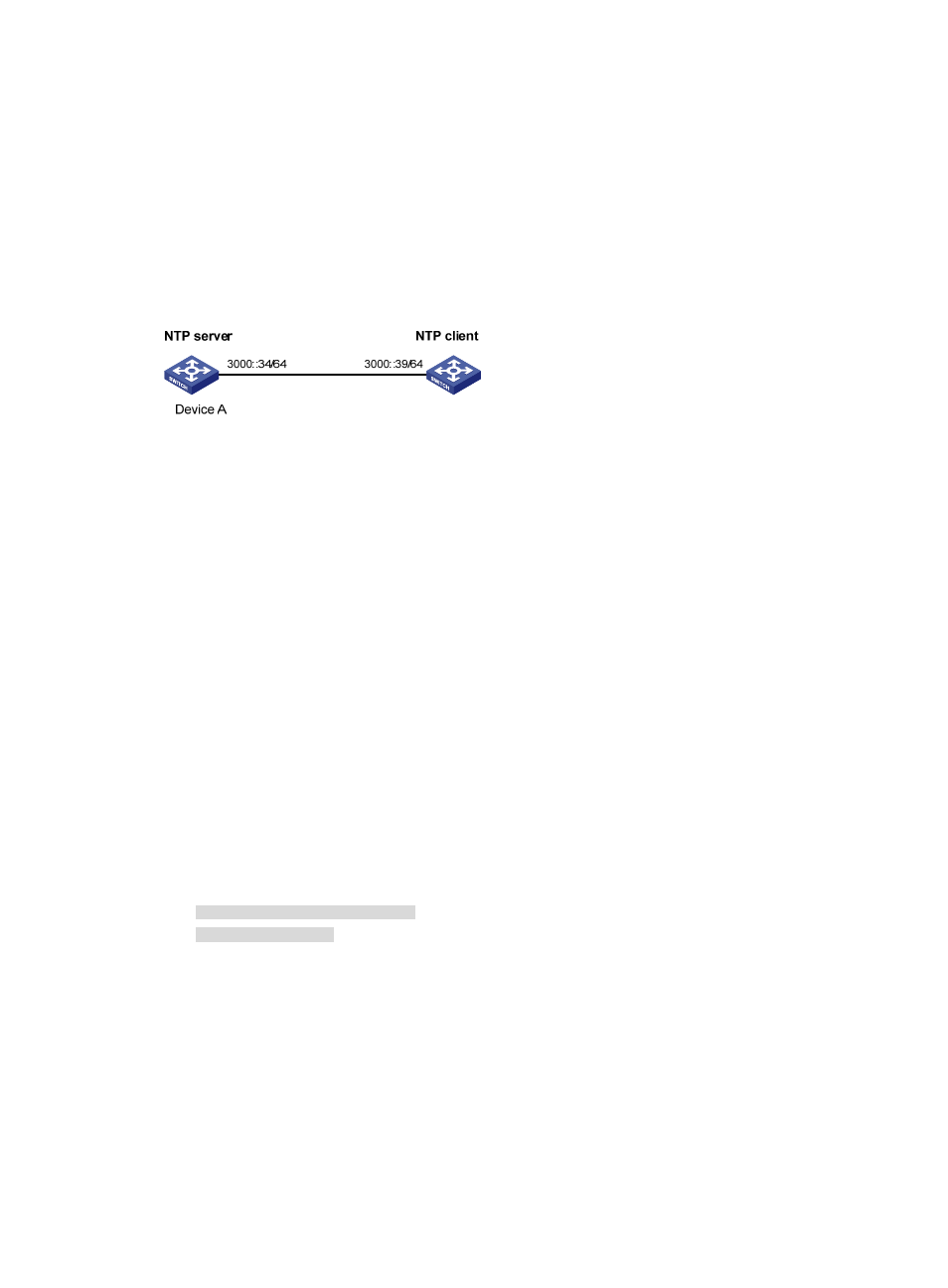
Network requirements
As shown in
, the local clock of Device A is to be used as a reference source, with the stratum level
2. Device B operates in client mode and Device A is to be used as the IPv6 NTP server for Device B.
Figure 9 Network diagram
Configuration procedure
1.
Set the IP address for each interface as shown in
. (Details not shown.)
2.
Configure Device A:
# Enable the NTP service.
<DeviceA> system-view
[DeviceA] ntp-service enable
# Specify the local clock as the reference source, with the stratum level 2.
[DeviceA] ntp-service refclock-master 2
3.
Configure Device B:
# Enable the NTP service.
<DeviceB> system-view
[DeviceB] ntp-service enable
# Specify Device A as the IPv6 NTP server of Device B so that Device B is synchronized to Device
A.
[DeviceB] ntp-service ipv6 unicast-server 3000::34
4.
Verify the configuration:
# Display the NTP status of Device B after clock synchronization.
[DeviceB] display ntp-service status
Clock status: synchronized
Clock stratum: 3
System peer: 3000::34
Local mode: client
Reference clock ID: 163.29.247.19
Leap indicator: 00
Clock jitter: 0.000977 s
Stability: 0.000 pps
Clock precision: 2^-10
Root delay: 0.02649 ms
Root dispersion: 12.24641 ms
Reference time: d0c60419.9952fb3e Wed, Dec 29 2010 19:01:45.598