Model and style number, Model and style number -5, Figure 1-2. style number identification chart -5 – Basler Electric BE1-25A User Manual
Page 15
MODEL AND STYLE NUMBER
BE1-25A Auto-Synchronizer style numbers define the features of a specific device. Each pair of
characters within the style number is associated with a specific feature or option that may be selected
from the style chart on the following page.
For example, if the first two digits of the style number are A2, the unit has the capability of deferring its
closure command to the breaker for any of the following reasons: (1) the bus is under a specified voltage;
(2) the bus is over a specified voltage; and (3) the bus-to-generator voltage is less than a selected value.
Another consideration: If a voltage matching option is desired (let assume it is), including one of the A
options is essential.
The second pair of digits determines the manner in which the Auto-Synchronizer commands the
generator to change speed. This relay uses option F5, which can initiate two different types of speed-
change commands: (1) proportional correction pulses, that are issued when the slip frequency is above
the allowable limit; and (2) target correction pulses, that automatically forces synchronization whenever
an out-of-phase condition coincides with a near-zero slip rate.
The third pair of digits selects the voltage matching capabilities that are required for an application. We
might look first at the voltage matching module with the most features, V3. Let examine these capabilities,
and how they might be useful to a specific application.
Option V3 (like Option V2) can automatically initiate corrective pulses to bring the generator voltage to
within the limits established by Option A1 or A2. However, when the voltage difference between bus and
generator is less than 20.0 volts, V3 has the additional capability of reducing the width of the corrective
pulses by an amount proportional to the correction required. This feature can significantly reduce
overshoot where inertia is particularly high (as in the control of sluice gates). If this is beneficial to our
hypothetical application (let assume it is) then the matter is decided: the third pair of digits is V3.
Finally, we choose D1 as the last pair of digits because we want the capability of obtaining a closure
when a dead bus is detected. (D1 also has the means of setting a threshold voltage to define a dead bus
condition.)
When ordering, it is recommended that the style number be preceded by the model number. Accordingly,
the style number now looks like (Figure 1-2):
BE1-25A A2 F5 V3 D1
where:
BE1-25A
= the model number
A2
= 3-parameter voltage restraint
F5
= both proportional correction pulse and target pulse capability
V3
= proportional correction pulse capability
D1
= automatic closure capability upon recognition of a dead bus
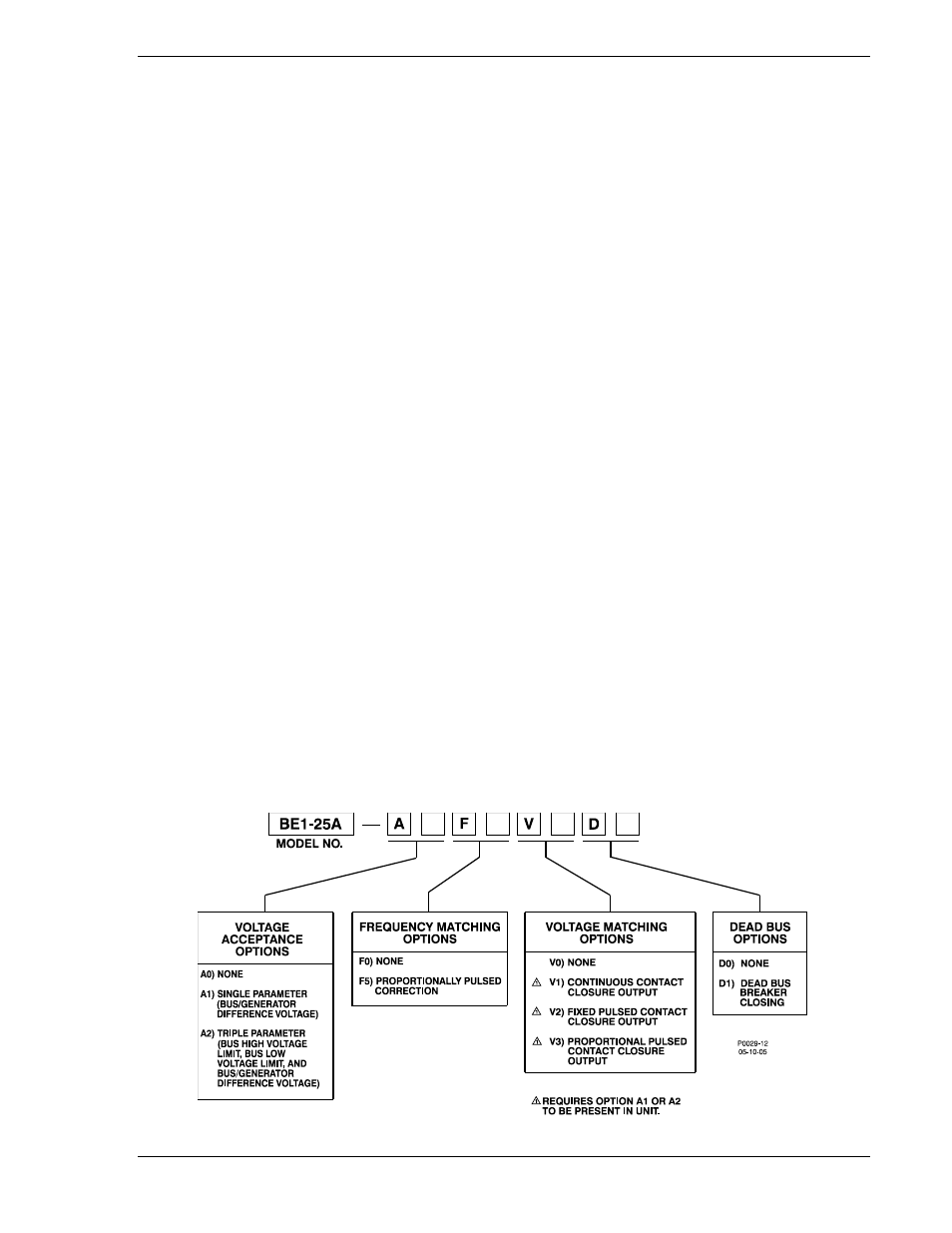
Figure 1-2. Style Number Identification Chart
9146600990 Rev S
BE1-25A General Information
1-5