Basler Electric BE1-25A User Manual
Page 23
6. GV>BV. When the test module is in the test position, provides the input terminals for a
simulated GV>BV contact closure. In the normal position, these jacks have no function.
7. DEAD BUS. When the module is in the test position, provides the input terminals for a
simulated Dead Bus Enable signal. (This signal is useful only if the Dead Bus option is
present.) In the normal position, these jacks have no function.
Locator C - POWER LED
LED lights to indicate that the power supply is operating correctly.
Locator D - LOAD/FUNCTION SELECT Switch
A three-position switch with the following two active positions. (The switch is spring loaded to the
center position.)
FUNCTION SELECT. Each time the switch is depressed, it advances the display (F) to show the next
register (in the sequence listed in SETTINGS/READINGS chart (E)). The leftmost character of the
display may be found in the left column of SETTINGS/READINGS chart which describes the use of
each register.
LOAD. Used to store data into memory. To do so, hold the switch in the raised position until the display
flashes (disappears and reappears) (this takes approximately 1 second). The data showing in the four
rightmost digits of the display is now recorded in memory.
Locator E - SETTINGS/READINGS Chart
This chart lists various computer registers that control the synchronizer or monitor the system. Each
register is identified by the associated character in the left-hand column of the chart. This digit also
appears as the left-most digit of display F whenever that register has been accessed by switch D
− i.e.,
the characters displayed in the rightmost digits of the display represent the generator selected or status
of the particular register identified by the character in the left column of the chart.
The SETTINGS registers are:
0 (GEN SELECT). When function 0 is selected, a — or a digit (1 through 6) appears as the rightmost
character. After powering up or after reset, a — appears, but once a generator is selected, a digit
appears. The appropriate character appears until the INCREMENT/DECREMENT switch is
incremented. The INCREMENT/DECREMENT switch must be held for approximately one-half second
for the change to occur. The sequence is from — to 1 and incrementing to 6, and then wrapping
around to 1.
After a generator is selected and the FUNCTION SELECT switch is depressed, the display changes to
indicate the setting number (1 through 6) in the leftmost position and the constant (value) in the four
rightmost display characters. If a setting is changed, it must be loaded by operating the LOAD switch.
1 (BREAKER TIME). These registers hold the characteristic operating times of the various breakers in
the system. Numbers may be entered to represent breaker operating time over the range of 0.02 to
0.800 seconds.
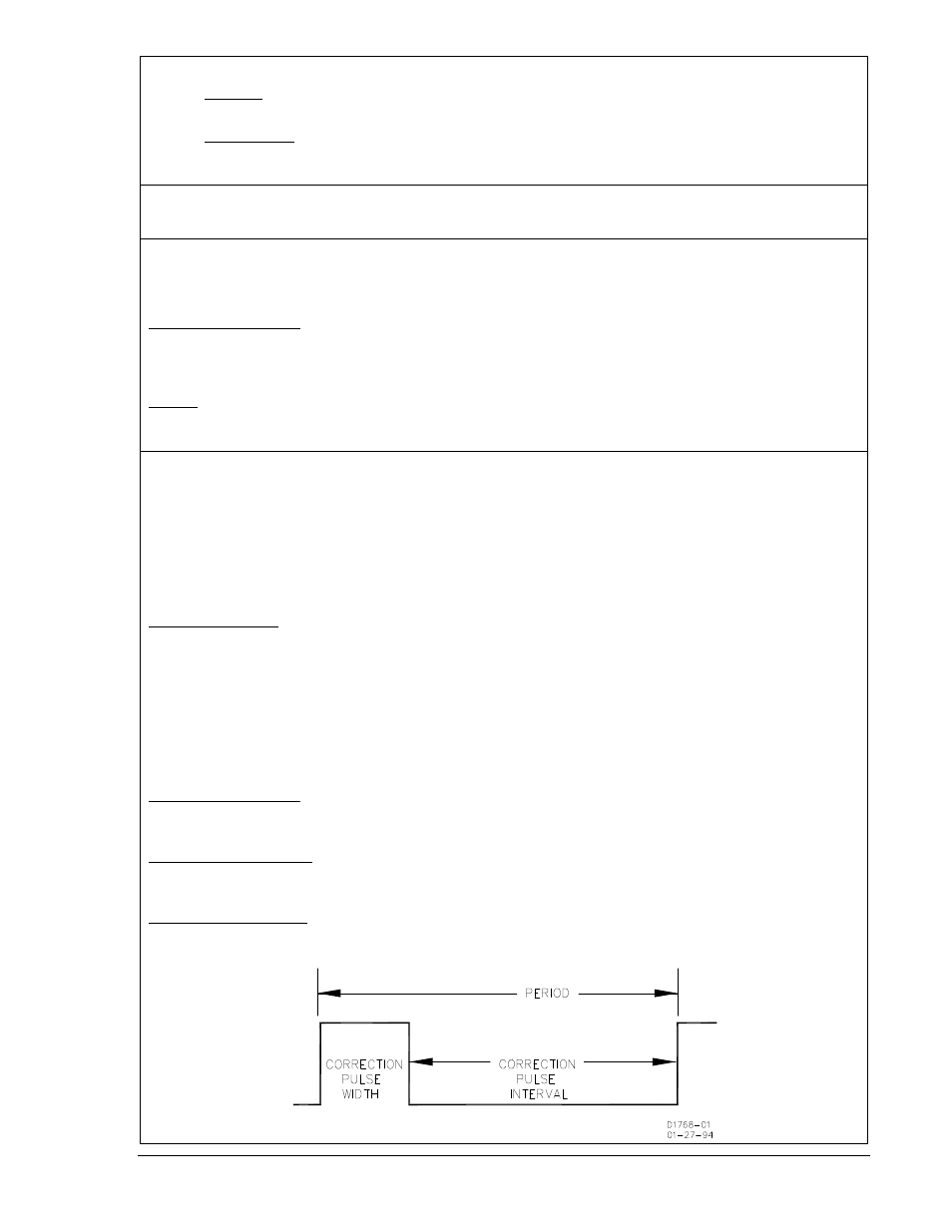
2 (CORRECT WIDTH). The number in this register represents the raise and lower speed correction
pulse width. The pulse width is settable from 0 to 99.9 seconds in 0.1 second increments. (Refer to
Figure 2-3.)
3 (CORRECT INTVL). The number in this register represents the raise and lower speed correction
pulse interval. The pulse interval is settable from 0 to 99.9 seconds in 0.1 second increments. (Refer to
Figure 2-3.)
9146600990 Rev S
BE1-25A Human-Machine Interface
2-3