Connections, General, Multi-generator operation – Basler Electric BE1-25A User Manual
Page 51: Connections -3, General -3, Multi-generator operation -3
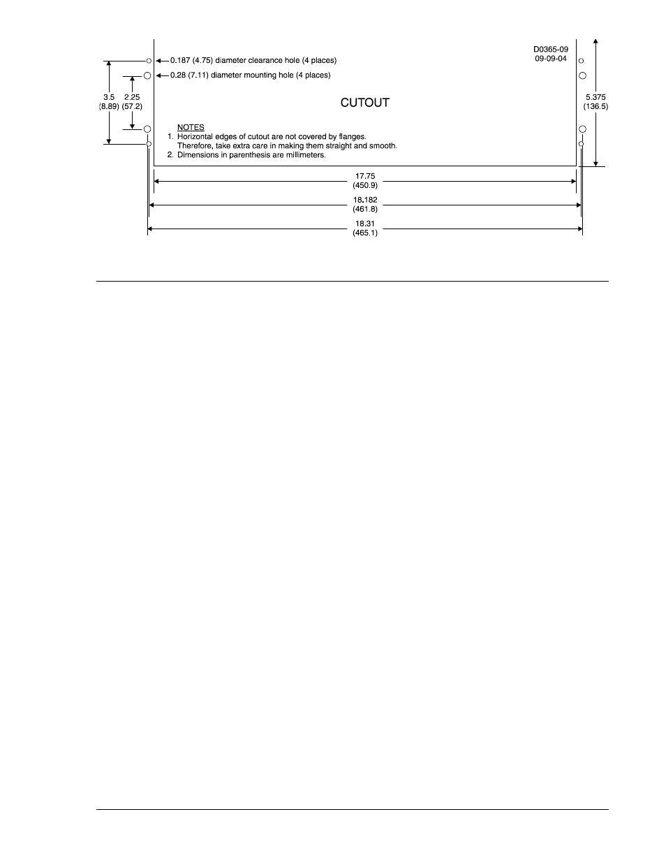
Figure 4-2. Cutout Dimensions (for Non-Rack Mounting)
CONNECTIONS
General
Incorrect wiring may result in damage to the unit. Connections for Auto-Synchronizer terminals are
identified in Figure 4-3. Terminals are suitable for use with wire sizes 14 AWG or larger.
When one BE1-25A unit is used to control more than one generator, refer to Multi-Generator Operation in
this section for a connection diagram.
Multi-Generator Operation
BE1-25A Auto-Synchronizers can be used on multiple-generator systems by simultaneously switching all
relevant inputs and outputs from one generator to the next. Figure 4-4 is an interconnect diagram for a
typical multiple-generator system controlled by one BE1-25A. This includes the generator sensing
voltage, the breaker 52b and closing coil circuits, and any leads associated with options (such as the
frequency and voltage matching lines to regulator or governor). Note that the closing time of each
generator breaker is entered into the memory of the BE1-25A, and is recalled by positioning the
SYNCHRONIZING SELECT SWITCH accordingly.
9146600990 Rev S
BE1-25A Installation
4-3