Voltage acceptance module a2, Frequency matching module f5, Voltage acceptance module a2 -6 – Basler Electric BE1-25A User Manual
Page 26: Frequency matching module f5 -6, Figure 2-5. module a2 -6 figure 2-6. module f5 -6
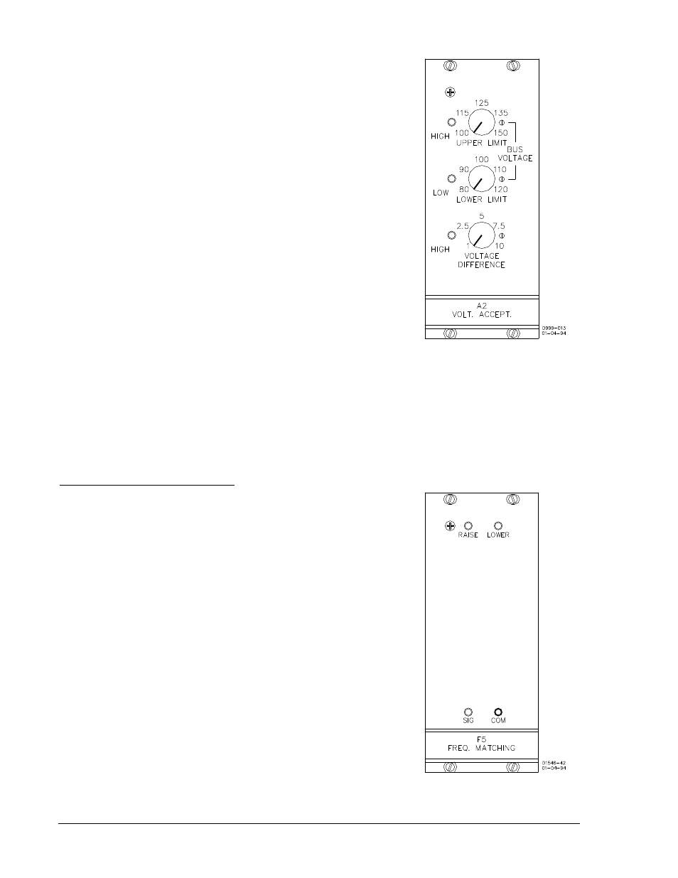
Voltage Acceptance Module A2
Voltage acceptance module A2 can use as many as three voltage
parameters to add constraints to the issuance of breaker
command signals. This option or option A1 is a prerequisite of,
and a controller of, any voltage matching option that may be
present. Figure 2-5 illustrates the following descriptions.
1. The UPPER LIMIT control establishes a maximum bus
voltage. No closure is to be attempted when the bus
voltage is above the upper limit.
2. The LOWER LIMIT control establishes a minimum bus
voltage. No closure is to be attempted when the bus
voltage is below the lower limit.
3. The VOLTAGE DIFFERENCE control establishes the
maximum acceptable voltage difference between the two
sides of the circuit breaker (generator voltage minus bus
voltage). No closure is to be attempted continuously
variable over the range of 1 to 10 Vac.
An LED to the left of each control lights whenever the associated
parameter is beyond the range set by the control. As a result, the
breaker closure is inhibited.
Figure 2-5. Module A2
Frequency Matching Module F5
The F5 frequency matching module (Figure 2-6) provides a frequency-corrective (speed) signal that is
compatible with motor-operated machine speed controls. Beginning on April 30, 1996, (BE1-25A, revision
R), the optional F5 frequency matching module includes the functionality of F1, F3, and F5 modes of
operation. The F1 mode of operation provides fixed width pulses, fired proportional to the slip frequency.
The F3 mode of operation provides a continuous correction signal until the measured slip is less than the
slip setting. The F5 mode of operation issues correction pulse width proportional to the slip frequency.
F1 Function, Pulse Contact Closure
The F1 function generates a fixed-width correction pulse settable
from 0.1 to 99.9 seconds in 0.1 second increments. These pulses,
though fixed in pulse width, are sent more often at higher slip
frequencies and less often as the slip decreases. In this (F5)
implementation, the fixed width pulse is fired proportional to the
slip frequency. The F1 function is implemented by setting the
correction pulse width to any non-zero value and setting the
correction pulse interval to zero. The F1 function provides a
continuous correction signal at high slip frequencies.
Approximately when the inverse of the slip frequency is greater
than the pulse width setting, the continuous correction signal will
become a fixed-width correction pulse with a pulse interval
approximately equal to the inverse of the slip frequency.
Correction pulses are issued until the slip frequency is within 0.5 of
the slip setting. Sync closure can occur any time below the slip
setting if no correction pulses are being issued.
Figure 2-6. Module F5
2-6
BE1-25A Human-Machine Interface
9146600990 Rev S