Voltage acceptance module a2, Voltage acceptance module a2 -7 – Basler Electric BE1-25A User Manual
Page 41
VOLTAGE ACCEPTANCE MODULE A2
Note: The first three paragraphs below repeat the material on the previous page.
The sensed bus and generator voltages are rectified and output to the balance circuit. Any inequality
detected in the balance circuit represents the voltage difference (
)V) between the bus and the generator.
And the polarity of the difference represents the direction required for any corrective signal to the
generator.
The balance error signal (or output) is amplified and directed to the precision full wave rectifier and to the
output gates. The output gates provide a signal (utilized by any voltage matching module present) that
indicates the desired direction that any speed-corrective command should have. This takes the form of
either a raise signal or a lower signal, according to the polarity of the error.
A comparator monitors the VOLTAGE DIFFERENCE control. If the voltage difference between the two
sides of the breaker (
)V) is found to be greater than the setting of the control, the breaker closure
command of the synchronizer is inhibited. (This information is also used by any voltage matching module
in the system to determine whether corrective signals are required.)
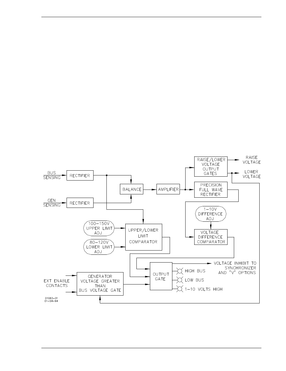
Module A2 differs from A1 by having additional comparators that monitor the UPPER LIMIT and the
LOWER LIMIT controls. The added circuitry serves to inhibit operation unless the bus voltage is less than
the upper limit, and greater than the lower limit. Additional circuits monitor the external enable contact.
The presence of a GV>BV signal (i.e., contact closed) inhibits the synchronizer closure output unless the
generator voltage is indeed greater than the bus voltage. See Figure 3-5.
Figure 3-5. Voltage Acceptance Module A2 Block Diagram
9146600990 Rev S
BE1-25A Functional Description
3-7