Voltage matching module v3, Voltage matching module v3 -11 – Basler Electric BE1-25A User Manual
Page 45
VOLTAGE MATCHING MODULE V3
Like the V2 module, module V3 issues corrective signals in the form of pulses to the generator control
system. The corrective signals are used to adjust the generator voltage toward the voltage of the bus. In
fact, this module is functionally identical to module V2 so long as the voltage difference between the two
sides of the breaker is greater than 20.0 Vac.
However, when the voltage difference is less than 20.0 Vac, the duration of the corrective pulses is
proportionally reduced from the duration called for by the setting of the CORRECTION PULSE WIDTH
control. I.e., the duration falls off by a ratio that is directly proportional to the reduced difference between
the two voltages.
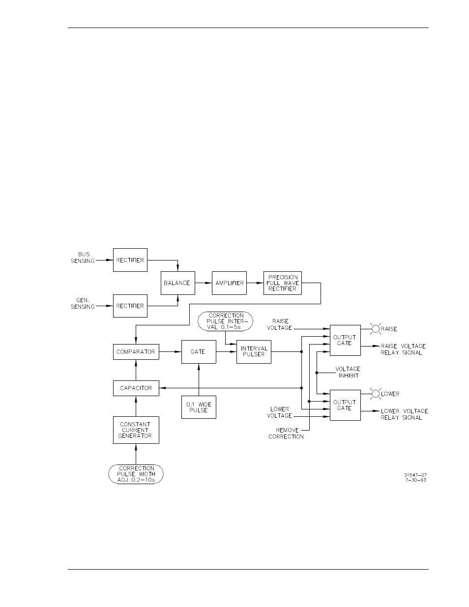
A constant current generator (Figure 3-9, bottom left) outputs a current that is used to charge a capacitor.
(The magnitude of the current is established by the CORRECTION PULSE WIDTH control.) The
comparator weighs the capacitor rising charge against the output of the precision full wave rectifier. The
interval pulse will then have the duration trimmed by an amount directly proportional to the capacitor
charge. This additional constraint is then input to the gate.
For other circuit features, refer to the functionally similar module V2 description on the previous page.
Module V3 is controlled by whichever voltage acceptance module (A1 or A2) is in the system. (Either A1
or A2 must be present in order for this module to function.) See Figure 3-9.
Figure 3-9. Voltage Matching Module V3 Block Diagram
9146600990 Rev S
BE1-25A Functional Description
3-11