Dead bus module d1, Dead bus module d1 -12, Figure 3-10. dead bus module d1 block diagram -12 – Basler Electric BE1-25A User Manual
Page 46
DEAD BUS MODULE D1
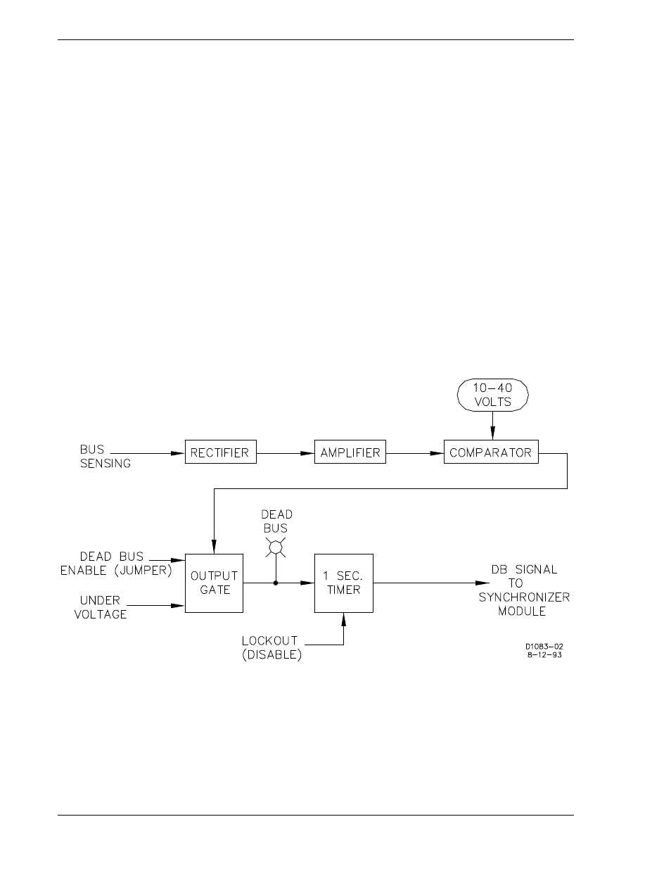
Sensed bus voltage (upper left of Figure 3-10) is rectified, scaled to logic levels, and then presented to
the comparator. The comparator determines whether or not the bus is dead, as defined by the setting of
the VOLTS control. Note that this control can define dead as any condition under a threshold setting in
the range of 10 to 40 volts.
If the bus voltage is less than the VOLTS control setting, the output gate logic is enabled. At this point, if
the output gate logic detects an enabling jumper (described below) and an undervoltage signal, the DEAD
BUS indicator is illuminated and the 1-second timer is started. If, for the ensuing second, the 1-second
timer continues to receive a qualifying signal from the output gate logic (and a lockout state is not
evidenced), a DB (dead bus) signal is passed to the MCU sync module, that causes the MCU sync
module to generate a breaker close signal.
This module is enabled by an external contact closure in one of three ways:
1. By an external jumper across the terminals 9 and 10 of terminal strip TB1 (on the rear of the case).
2. By a manually-controlled external switch (same terminals).
3. By an automatically controlled enabling signal (same terminals).
Figure 3-10. Dead Bus Module D1 Block Diagram
3-12
BE1-25A Functional Description
9146600990 Rev S