Verification testing options, General, Voltage acceptance module a1 verification test – Basler Electric BE1-25A User Manual
Page 65: Verification testing options -9, General -9, Voltage acceptance module a1 verification test -9
hertz. (b) Set generator 5 breaker time to the maximum value — 0.800 seconds. (c) Turn the
GENERATOR SELECT knob to 5. (d) Set the display to read setting A (ADV ANGLE).
Step 26. Short the 52b jacks to simulate breaker open. There should be no illumination of the SYNC
LED, and the ADV ANGLE setting should display dashes to indicate that the required advance
angle is beyond range.
Step 27. While monitoring the phase difference between generator and bus with a phase angle meter,
set generator 5 breaker time 0.500. Set the display to read ADVance ANGLE and wait 15
seconds. The SYNC LED should pulse ON/OFF, and the ADVance ANGLE setting should read
36
±3° at sync.
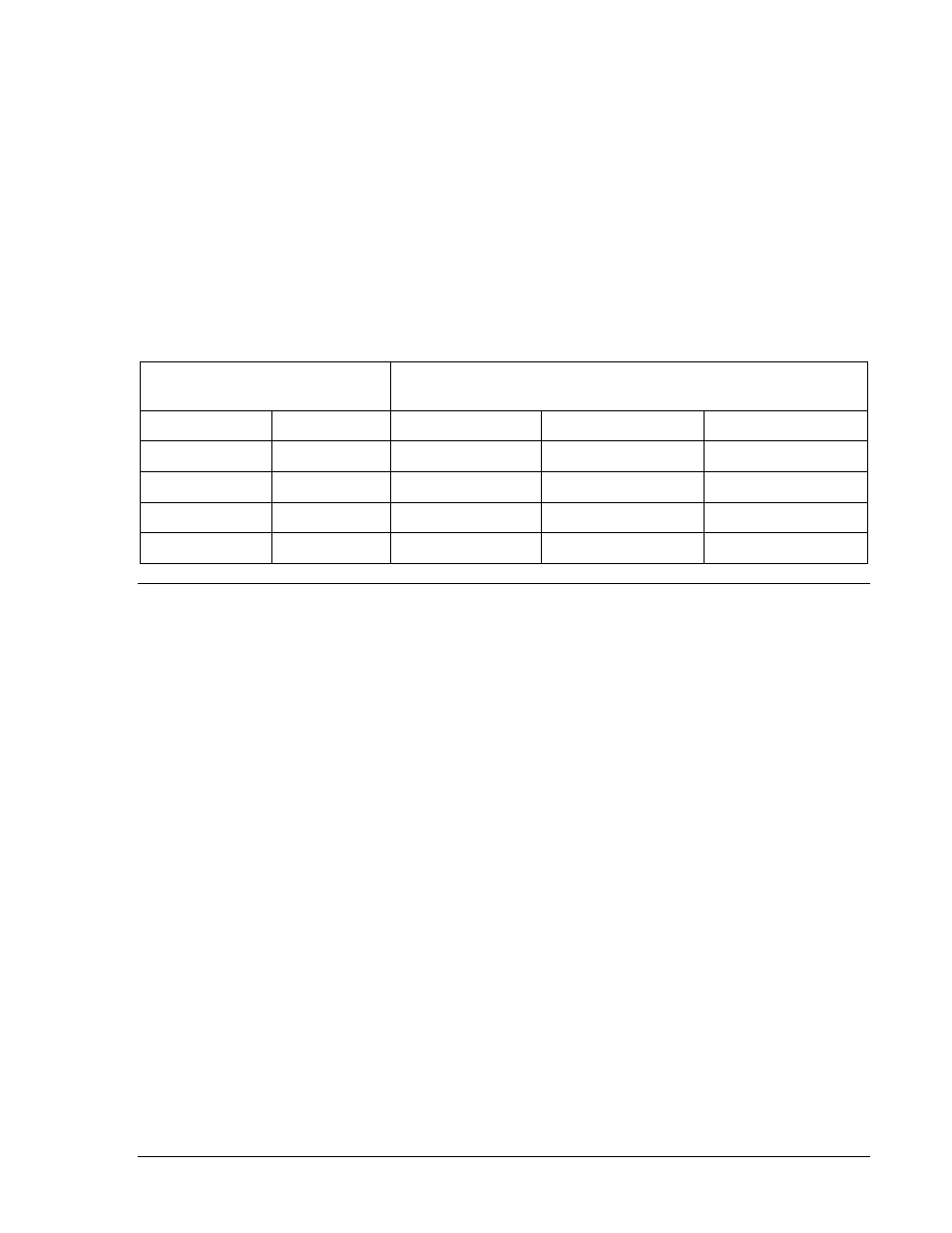
Step 28. To check that the advance angle is within specified accuracy, use the set up parameters given
in Table 5-1. When running the tests, the phase angle meter should provide the indicated
readings within
±3°. Note that no Breaker Closure output will occur when the parameters are
such that the advance angle is beyond 40
°.
Table 5-1. Advance Angle Test Parameters
(Maximum slip rate must be set at 0.5000 Hz.)
Sensed Generator Frequency
(With Bus at 60.00 Hz.)
Advanced Angle (
±3°) for Indicated Breaker Closing Times
Gen. Under
Gen. Over
100 ms
400 ms
700 ms
59.6
60.4
14.4
°
No Sync
No Sync
59.8
60.2
7.2
°
28.8
°
No Sync
59.98
60.02
0.72
°
2.88
°
5.04
°
59.995
60.005
0.18
°
0.72
°
1.26
°
VERIFICATION TESTING OPTIONS
General
Before performing any of the following procedures for the first time, be sure to review the paragraphs
entitled VERIFICATION AND CALIBRATION, General. There you will find preliminary instructions that are
common to virtually all test and calibration procedures. Also, you will find many terms defined, a list of
recommended equipment, and two basic setup diagrams. Test procedures for discontinued options B3,
B5, F1, F2, F3, F4, and V4 are provided in Section 6.
Voltage Acceptance Module A1 Verification Test
The VOLTAGE DIFFERENCE control is calibrated in terms of percentage, using the bus voltage as a
reference. The following definitions apply.
∆∆𝑉 = |𝑉
𝐵𝑈𝑆
− 𝑉
𝐺𝐸𝑁𝐸𝑅𝐴𝑇𝑂𝑅
|
ΔV% = the setting of the VOLTAGE DIFFERENCE control
= 100|𝑉
𝐵𝑈𝑆
− 𝑉
𝐺𝐸𝑁𝐸𝑅𝐴𝑇𝑂𝑅
|/𝑉
𝐵𝑈𝑆
Step 1. Perform the test setup illustrated in Figure 5-1, and move the test module into the offset (i.e.,
test) position.
Step 2. Set the simulated bus voltage and the simulated generator voltage (at the voltage sensing
inputs) to 120 V, 60 hertz. Rotate the VOLTAGE DIFFERENCE control of the A1 module to the
minimum setting (0.5%).
Step 3. Slowly adjust the generator voltage to 0.6
±0.3 V above, and then to 0.6 ±0.3 V below the initial
120 Vac setting. The
ΔV HIGH LED should turn ON whenever above or below this range.
Step 4. Repeat steps 2 and 3 with the VOLTAGE DIFFERENCE control at maximum (5%). The
∆V
HIGH LED should turn ON whenever the generator voltage swings 6 V (
±1%) above or below
the initial 120 Vac position.
9146600990 Rev S
BE1-25A Testing
5-9