Voltage matching module v1 -10 – Basler Electric BE1-25A User Manual
Page 29
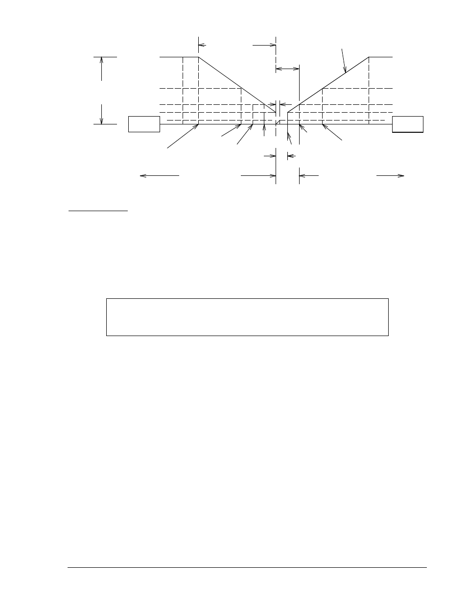
Figure 2-9. Proportional Relationship when GF>BF Switch is Closed
Phase Correction
A target pulse is issued to the correction pulse train when the bus and generator are frequency matched
(within approximately six percent of the maximum slip setting) but not phase matched. The pulses are
steered to induce a slip frequency that may be adjusted to fall within the allowable limits of the correction
pulse train. The contacts of one relay are used to signal the generator to raise speed, while the contacts
of the other relay are used to signal the generator to lower its speed. The target pulses issued may be
monitored at the SIG and COM jacks and are additional pulses to the correction pulse train. (+5 Vdc =
raise pulse;
−5 Vdc = lower pulse.)
1/2 Max Slip
1/2 Max Slip
Max Slip
4 * Max Slip
12.5%
25%
50%
2 * Max Slip
100%
50%
25%
12.5%
Max Slip
Pos Slip
(GF>BF)
100%
Target Slip
Band
Min Slip &
Sync Range
Percentage Correction
Pulse Width
Neg Slip
(GF<BF)
Slip Inhibit LED On
Slip Inhibit LED On
Zero Slip
Correction Width
Setting Value
Frequency Correction
Dead Band
Proportional
Correction
Correction Width
Setting Value
Proportional Correction
3-1/2 * Max Slip
1-1/2 * Max Slip
D2610-05
10-06-97
NOTE
If the generator voltage is less than the generator undervoltage setting,
correction pulses are inhibited.
9146600990 Rev S
BE1-25A Human-Machine Interface
2-9