Figure 5-2. test setup for installed unit -5 – Basler Electric BE1-25A User Manual
Page 61
Step 1. Loosen the (4) screws that secure the test module and extract it from the case. This removes
external electrical connections at TB1 of the BE1-25A.
Step 2. Note that two sets of tracks have been provided for the test module. Carefully enter the module
into the right-hand tracks (upper and lower), and gently push the module forward. (If a bind or
obstruction is felt, pull the module back slightly and check that it is properly entered into the
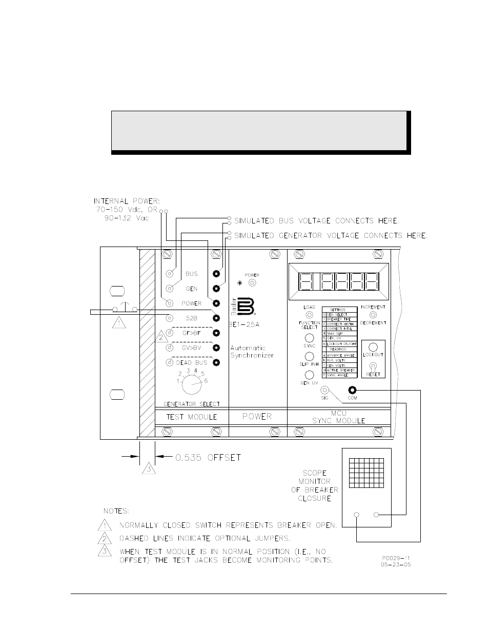
right-hand pair of tracks.) Figure 5-2 shows the module fully entered into the offset—or test
mode—position.
Step 3. Apply operating power to the BE1-25A through the POWER jacks of the test module. The power
supply module POWER LED should be ON to indicate that the BE1-25A unit is functioning.
Figure 5-2. Test Setup for Installed Unit
WARNING!
Do NOT apply Test power to tip-plugs until they are inserted into the test module
POWER jacks.
9146600990 Rev S
BE1-25A Testing
5-5