Voltage matching module v1, Voltage matching module v1 -9 – Basler Electric BE1-25A User Manual
Page 43
VOLTAGE MATCHING MODULE V1
Module V1 issues corrective signals to the generator control system that cause the voltage to approach
the voltage of the bus. The corrective output signal is in the form of a continuous contact closure.
This module is, in turn, controlled by whichever voltage acceptance module is in the system. (One of
these, either A1 or A2 must be present in order for module V1 to function.)
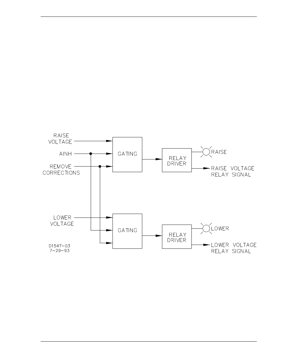
An inhibit signal from the A module, AINH, will disable the V1 output (Figure 3-7). Additional A-module
signals, raise and lower, determine whether the output will raise or lower the generator voltage.
If the generator voltage is less than the generator undervoltage setting, voltage correction pulses are
inhibited. See Figure 3-7.
Figure 3-7. Voltage Matching Module V1 Block Diagram
9146600990 Rev S
BE1-25A Functional Description
3-9