Basler Electric BE1-25A User Manual
Page 28
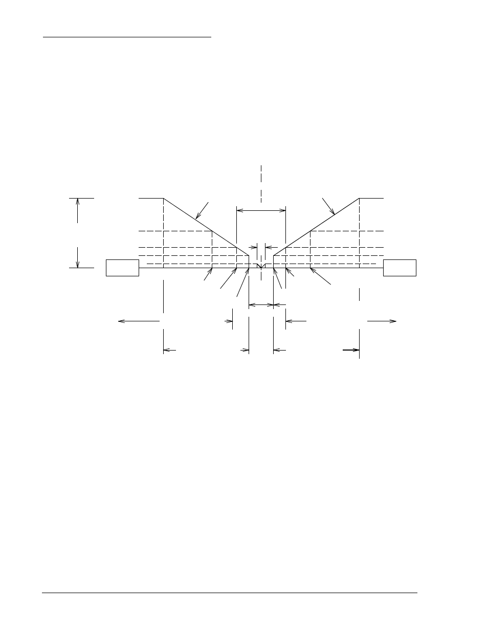
F5 Function, Proportional Frequency Correction
A proportional correction pulse train is issued when the slip frequency is greater than 50 percent of the
maximum slip frequency setting. The pulses are steered (as appropriate) to operate one of the two speed-
adjust output relays. The contacts of one relay are used to signal the generator to raise speed, while the
contacts of the other relay are used to signal the generator to lower its speed. The period of the correction
pulses is determined by the settings loaded into the microprocessor. That is, the period is equal to the
sum of the correction pulse interval plus the correction pulse width. The period remains constant once the
correction pulse width and correction pulse interval are set. The proportional correction pulse is
determined by the percent of correction required. If the slip frequency is greater than four times the
maximum slip allowed, the proportional correction pulse train is at 100 percent of the setting (correction
pulse interval setting plus correction pulse width setting). If the slip frequency is equal to the maximum
slip setting, the proportional correction pulse width is at 25 percent of the original setting. The correction
pulse interval (wait time) will increase to maintain a consistent correction pulse period (total of the pulse
interval and pulse width). Figure 2-8 shows the proportional relationship when the GF>BF switch is open.
Figure 2-8. Proportional Relationship when GF>BF Switch is Open
Proportional correction is linear between 100 percent (four times maximum slip frequency setting) and
12.5 percent (equal to one-half maximum slip frequency setting). Synchronization is enabled at slip
frequencies less than the maximum slip setting. Although synchronization is enabled at slip frequencies
below 50 percent of the maximum slip allowed, no correction pulses are issued. The pulses issued by this
option (to direct the output relays) may be monitored at the SIG and COM jacks. (+5 Vdc = raise pulse;
−5 Vdc = lower pulse.) Figure 2-9 shows the proportional relationship when the GF>BF switch is closed.
Max Slip
4 * Max Slip
4 * Max Slip
12.5%
25%
50%
2 * Max Slip
100%
50%
25%
12.5%
Max Slip
2 * Max Slip
Pos Slip
(GF>BF)
100%
Target Slip
Band
Min Slip &
Sync Range
Zero Slip
Correction Width
Setting Value
Correction Width
Setting Value
Percentage Correction
Pulse Width
Neg Slip
(GF<BF)
Slip Inhibit LED On
Slip Inhibit LED On
Proportional Correction
Proportional Correction
1/2 Max Slip
1/2 Max Slip
Frequency Correction Dead Band
Proportional Correction
Range
Proportional Correction
Range
D2610-08
10-03-97
2-8
BE1-25A Human-Machine Interface
9146600990 Rev S