Automatic synchronizer, Functional description, Automatic synchronizer -4 – Basler Electric BE1-25A User Manual
Page 74: Functional description -4, Figure 6-3. synchronizer module -4
AUTOMATIC SYNCHRONIZER
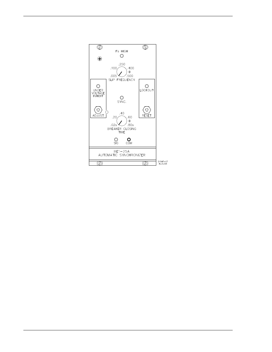
BE1-25A Auto-Synchronizers, serial number 299 and previous use the synchronizer module shown in
Figure 6-3. A functional description and calibration instructions are provided in the following paragraphs.
Figure 6-3. Synchronizer Module
Functional Description
See Figure 6-4 to follow the functional description. The sensed bus and generator sine wave voltages are
input to the separate Square Wave Generators.
The square wave generators' outputs are used by the generator frequency greater than bus frequency
circuit. The generator and bus frequencies are compared and, if the external GF>BF switch is closed and
the bus frequency is higher, the GF>BF signal is output to inhibit the sync circuits until the generator
frequency is greater than the bus frequency. This allows the generator to pick up load more quickly.
The exclusive-or circuit outputs a pulse that has a width proportional to the phase difference. The pulse is
then input to a low pass filter and converted to a triangular waveform whose instantaneous amplitude is
proportional to the phase difference of the input square waves. The low pass filter waveform is input to
the breaker time compensation circuit, the 40° inhibit sync circuit, and the differentiator.
6-4
BE1-25A Relay Differences
9146600990 Rev S