Voltage matching module v1, Voltage matching module v2, Voltage matching module v2 -10 – Basler Electric BE1-25A User Manual
Page 30
Voltage Matching Module V1
Option V1 (Figure 2-10) issues a corrective signal whose purpose
is to increase or decrease the generator terminal voltage to within
the voltage difference limit determined by the setting of the
Voltage Acceptance Option A1 or A2 (whichever is present). The
signal is in the form of a continuous closed-contact output.
Control and indicators are limited to:
a. RAISE LED, that lights when a raise voltage signal is
being output (at which time the raise output contact is
closed).
b. LOWER LED, that lights when a lower voltage signal is
being output (at which time the lower output contact is
closed).
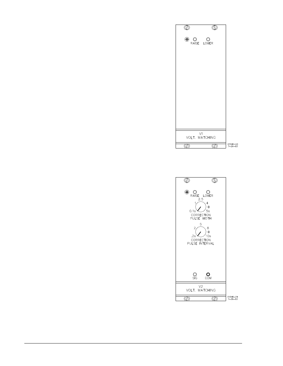
Figure 2-10. Module V1
Voltage Matching Module V2
Option V2 (Figure 2-11), like option V1, issues corrective signals
that increase or decrease the generator voltage to within the
voltage difference limit determined by the setting of whichever
Voltage Acceptance option is present (A1 or A2). In the case of
this option, however, the corrective signal is not continuous (as in
V1), but rather is in the form of a pulsing output contact.
Pulse duration and interval are independently controlled by the
CORRECTION PULSE WIDTH control, and by the CORRECTION
PULSE INTERVAL control.
When correction pulses are issued, the direction of the correction
is indicated by either the RAISE or the LOWER LED. This also
indicates which of the two output relays (and which set of output
contacts) is delivering the pulses: the raise output relay or the
lower output relay.
The pulses issued by this option (to direct the output relays) may
be monitored at the SIG and COM jacks. (+12 Vdc = relay de-
energized; 0 Vdc = relay energized.)
Figure 2-11. Module V2
2-10
BE1-25A Human-Machine Interface
9146600990 Rev S