Description and application, Frequency matching module f1, Frequency matching module f3 – Basler Electric BE1-25A User Manual
Page 80: Description and application -10, Frequency matching module f1 -10, Frequency matching module f3 -10
FREQUENCY MATCHING MODULES (OPTIONS F1, F2, F3, AND F4)
Description and Application
When the oncoming generator frequency is not within the paralleling tolerance, but is within +20% or
−40% of the bus frequency, one of the frequency matching options − F1, F2, F3, or F4 − can supply a
correction signal to the prime mover governor to adjust the generator speed to within the required
paralleling tolerance.
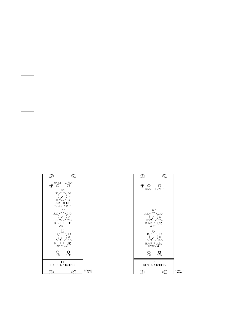
Frequency Matching Module F1
Option F1 (Figure 6-9) provides a speed-corrective signal that is compatible with motor-operated controls
of machine speed. The signal can operate in two modes, depending upon slip rate and phasing.
Mode 1
A correction pulse train is issued when the slip frequency is greater than the allowable limit. The pulses
are steered (as appropriate) to operate one of the two speed-adjust output relays. The contacts of one
relay are used to signal the generator to raise speed, while the contacts of the other relay are used to
signal the generator to lower its speed. The frequency of the correction pulses is identical to the slip
frequency, while the width of the pulses is governed by the CORRECTION WIDTH PULSE control that
has a range of 0.1 to 1.0 seconds.
Mode 2
In the event that generator and bus are frequency matched but not phase matched, bump pulses are
issued to induce a slip frequency that, in turn, may be adjusted to fall within the allowable limit by means
of mode-1 correction pulses. The bump pulses are matched to system requirements by the BUMP PULSE
WIDTH and the BUMP PULSE INTERVAL controls (Figure 6-9). Bump pulses and control pulses share
the same output relays: one for raise speed, the other for reduce speed. They also share the same
indicators. As the output commands are issued, the two LED indicators, RAISE and LOWER, illuminate
accordingly. The pulses issued by this option (to direct the output relays) may be monitored at the SIG
and COM jacks. (+12 Vdc = relay de-energized; 0 Vdc = relay energized.)
Frequency Matching Module F3
Option F3 (Figure 6-10) is identical to Option F1, described previously, except that the F3 mode-1
correction signal is continuous rather than pulsed.
Figure 6-9. Module F1
Figure 6-10. Module F3
6-10
BE1-25A Relay Differences
9146600990 Rev S