Description and application, Functional description, Description and application -8 – Basler Electric BE1-25A User Manual
Page 78: Functional description -8, Figure 6-5. module b3 -8 figure 6-6. module b5 -8
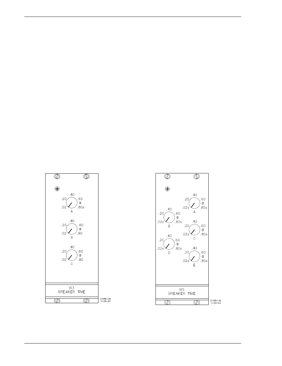
BREAKER TIME EQUALIZATION MODULES (OPTIONS B3 AND B5)
Beginning with serial number 300, options B3 and B5 were discontinued. For reference purposes,
portions of an earlier edition of this manual that covered these discontinued options are reprinted in the
following paragraphs.
Description and Application
Two breaker time equalization options (Figures 6-5 and 6-6) provide individually adjustable time delays
that may be adjusted to match the characteristic closing times of the controlled breakers. Option B3
provides three additional time delays, while option B5 provides five additional delays (i.e., additional to the
one that is present without any option).
These options are not currently offered because their function was incorporated in the MCU synchronizer
module (beginning with chassis serial number 300).
Functional Description
(Refer to Figures 6-7 and 6-8.) A remote selector switch is used to select and enable the Transmission
Gate to be used. All gates are inhibited except the one selected.
The signal from the Breaker Time Timer (of the Synchronizer Module) is delivered to the front panel TIME
SET controls, and then to the Transmission Gates.
The Advance Angle signal (from the Breaker Time Compensation circuit of the Synchronizer Module) is
delivered to the front panel TIME SET controls, and then to the Transmission Gates. The Transmission
Gate output of the selected breaker is then used to determine when the Breaker Close signal is
generated.
Figure 6-5. Module B3
Figure 6-6. Module B5
6-8
BE1-25A Relay Differences
9146600990 Rev S