Introduction, Section 2, Human-machine interface -1 – Basler Electric BE1-25A User Manual
Page 21: Introduction -1, Figure 2-1. location of controls and indicators -1
Advertising
SECTION 2
• HUMAN-MACHINE INTERFACE
INTRODUCTION
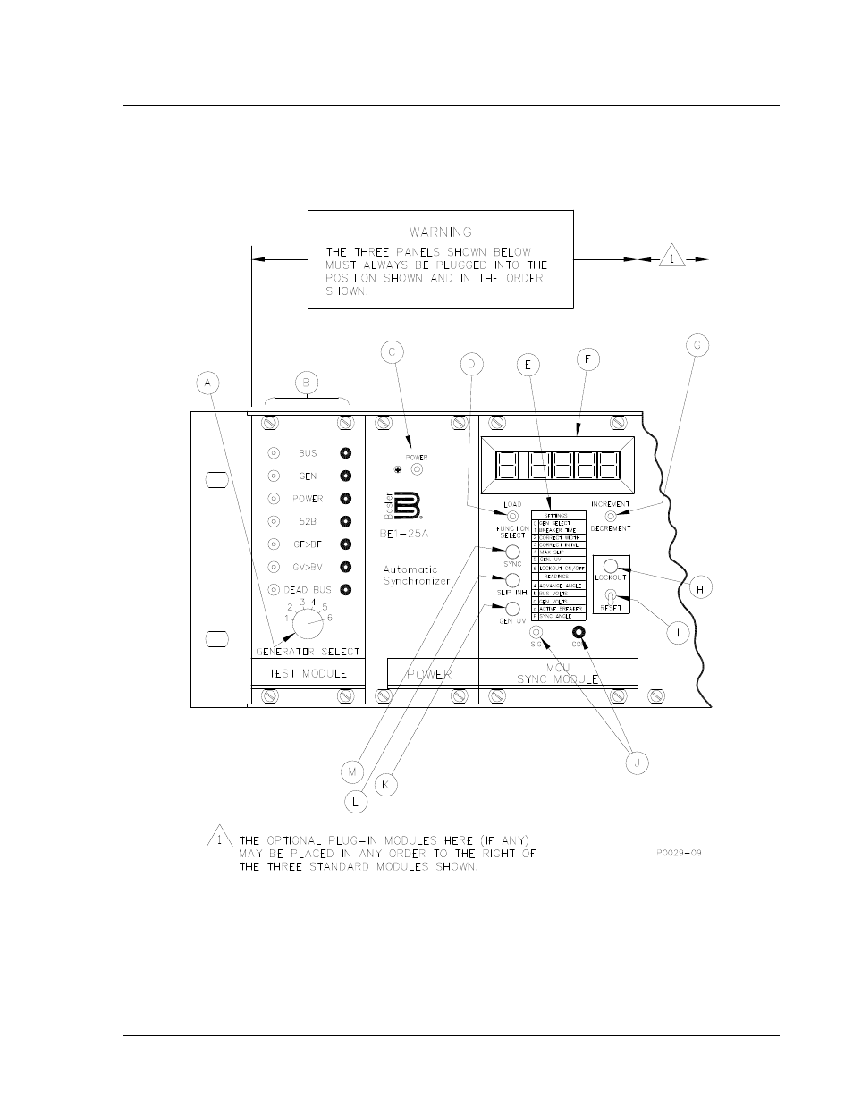
A basic BE1-25A Synchronizer (without options) is shown in Figure 2-1 and described in Table 2-1.
Figure 2-2 shows the Test Module in its offset position as required for testing. The remaining figures
describe the various options currently available.
Figure 2-1. Location of Controls and Indicators
9146600990 Rev S
BE1-25A Human-Machine Interface
2-1
Advertising