F2 and f4 calibration, F2 and f4 calibration -13 – Basler Electric BE1-25A User Manual
Page 83
Advertising
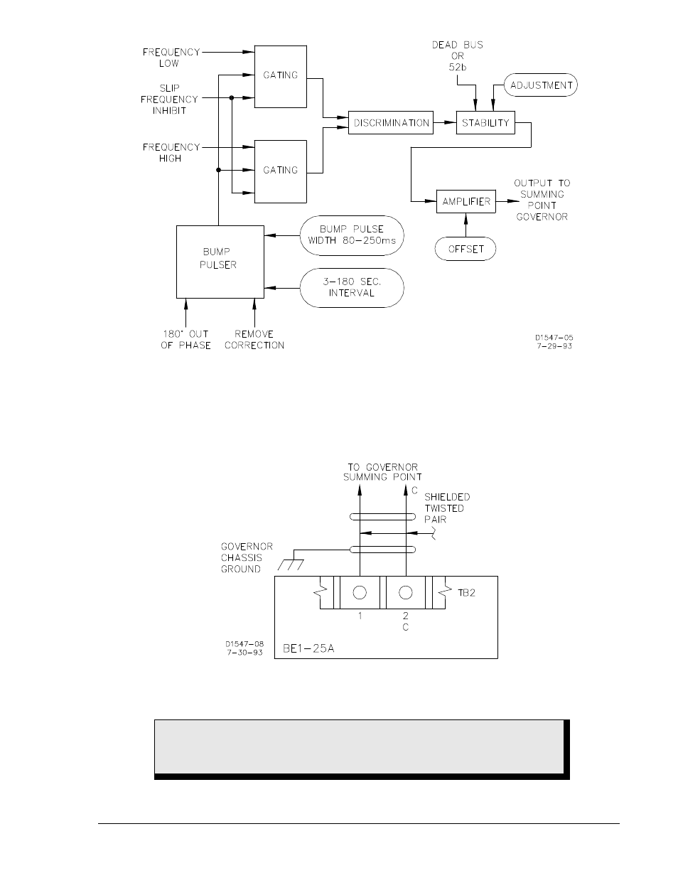
Figure 6-14. Module F4 Block Diagram
F2 and F4 Calibration
1. Connect module F2 or F4 in accordance with Figure 6-15.
Figure 6-15. Connection Diagram for F2 and F4 Modules
WARNING!
Do not attempt to use options F2 or F4 in any chassis of serial number 300 and
up. On these units, terminal 1 is ground for the chassis.
9146600990 Rev S
BE1-25A Relay Differences
6-13
Advertising
See also other documents in the category Basler Electric Accessories for electrical:
- SMC-250 (6 pages)
- AVC63-2 (2 pages)
- AVC63-2.5 (2 pages)
- AVC63-4D (6 pages)
- AVC63-7 (4 pages)
- AVC63-7F (4 pages)
- AVC Sensing Module (2 pages)
- AVC125-10 (10 pages)
- AVC125-10 (14 pages)
- APR63-5 (6 pages)
- APR63-5X (4 pages)
- DECS-400 (250 pages)
- BE350 (4 pages)
- VR63-4/UL (2 pages)
- VR63-4A/UL (4 pages)
- VR63-4B (2 pages)
- VR63-4C/UL (2 pages)
- BE300PM (4 pages)
- DECS-100 (86 pages)
- DECS-250N Terminals and Connectors (370 pages)
- DECS-250 Mounting (4 pages)
- DECS-250N Mounting (4 pages)
- MVC232 (4 pages)
- MVC112 (8 pages)
- MVC236 (24 pages)
- BE2000E (82 pages)
- MVC300 (16 pages)
- CBS 212A (28 pages)
- MVC301 (16 pages)
- ICRM-15 (4 pages)
- DGC-2020 Troubleshooting (620 pages)
- DGC-2020ES (252 pages)
- DGC-2020HD (404 pages)
- DGC-2020ES Mounting (2 pages)
- DGC-2020HD Modbus Protocol (318 pages)
- RDP-110 (26 pages)
- IDP-800 (70 pages)
- ESD201 (4 pages)
- ESD202 (2 pages)
- IDP-1200 (90 pages)