System operation, Section 3, Functional description -1 – Basler Electric BE1-25A User Manual
Page 35: System operation -1, Figure 3-1. system block diagram -1
SECTION 3
• FUNCTIONAL DESCRIPTION
SYSTEM OPERATION
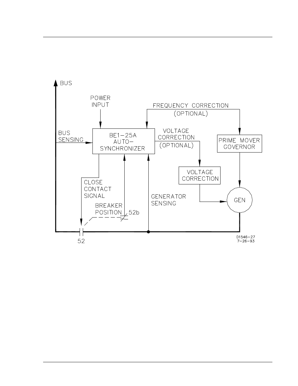
As the prime mover brings the oncoming generator up to speed, the BE1-25A Auto-Synchronizer (Figure
3-1) compares the generator output with the bus. When the monitored frequency and phase angle (and,
optionally, the voltage) are within preset limits as described below,
the BE1-25A Auto-Synchronizer
signals the controlled breaker to close.
Figure 3-1. System Block Diagram
To accomplish closure quickly and with the least stress on the system, a microprocessor in the MCU sync
module calculates (and thus anticipates) the advance angle necessary to compensate for breaker closure
time, as well as for operation time of the output relay. To do so, it utilizes data stored in memory
concerning the characteristic closing times of the generator breaker to which it is connected.
As detailed in Section 4, the BE1-25A Auto-Synchronizer can be set-up to control multiple generators.
Each generator may be associated with a breaker whose closing time may be different from the others.
The various closing times are stored in the synchronizer memory and called up according to which
generator/breaker combination the BE1-25A Auto-Synchronizer is connected. (The connecting is
performed by user-installed switches.)
After breaker closure has been initiated, the Auto-Synchronizer is inhibited from further operation for 15
±1.5 seconds.
9146600990 Rev S
BE1-25A Functional Description
3-1