Voltage matching module v1 verification test, Voltage matching module v2 verification test, Voltage matching module v3 verification test – Basler Electric BE1-25A User Manual
Page 67: Voltage matching module v1 verification test -11, Voltage matching module v2 verification test -11, Voltage matching module v3 verification test -11, Figure 5-3. option v2 waveform -11
time of the F5 module RAISE LED (time should be approximately 7.5 seconds). Total time for
ON and OFF is approximately 10.0 seconds. Observe that the SLIP INH LED is ON.
Step 6. Increase the generator frequency until the SLIP INH LED goes OUT (should be approximately
59.75 hertz). This should be the point at which synchronization is enabled.
Step 7. Continue to increase the generator frequency until the SYNC LED flashes. Observe that the
generator frequency is greater than 59.75 hertz.
Step 8. Increase the generator frequency to 60 hertz. Observe the SYNC ANGLE (register P) on the
MCU display. If the display indicates a negative angle, then raise pulses are issued. If the
display indicates a positive angle, then lower pulses are issued. The pulse period (total time for
ON and OFF) should be approximately 10.0 seconds.
Voltage Matching Module V1 Verification Test
An A1 or A2 module must be installed to perform this test.
Step 1. Provide the test setup illustrated in Figure 5-1, and move the test module into the offset (i.e.,
test) position.
Step 2. Set the simulated generator voltage to a value that is higher than the bus by an amount that
exceeds the option A VOLTAGE DIFFERENCE control setting. The LOWER LED should be
ON.
Step 3. Set the simulated generator voltage to a value that is lower than the bus by an amount that
exceeds the Option A VOLTAGE DIFFERENCE control setting. The RAISE LED should be ON.
Step 4. Randomly check one or two points where the difference is less than the option A voltage
difference.
Neither of the LEDs should be ON.
Voltage Matching Module V2 Verification Test
An A1 or A2 module must be installed to enable this option.
Step 1. Provide the test setup illustrated in Figure 5-1, and move the test module into the offset (i.e.,
test) position.
Step 2. Set the simulated generator voltage to a value that is higher than the bus by an amount that
exceeds the option A VOLTAGE DIFFERENCE control setting.
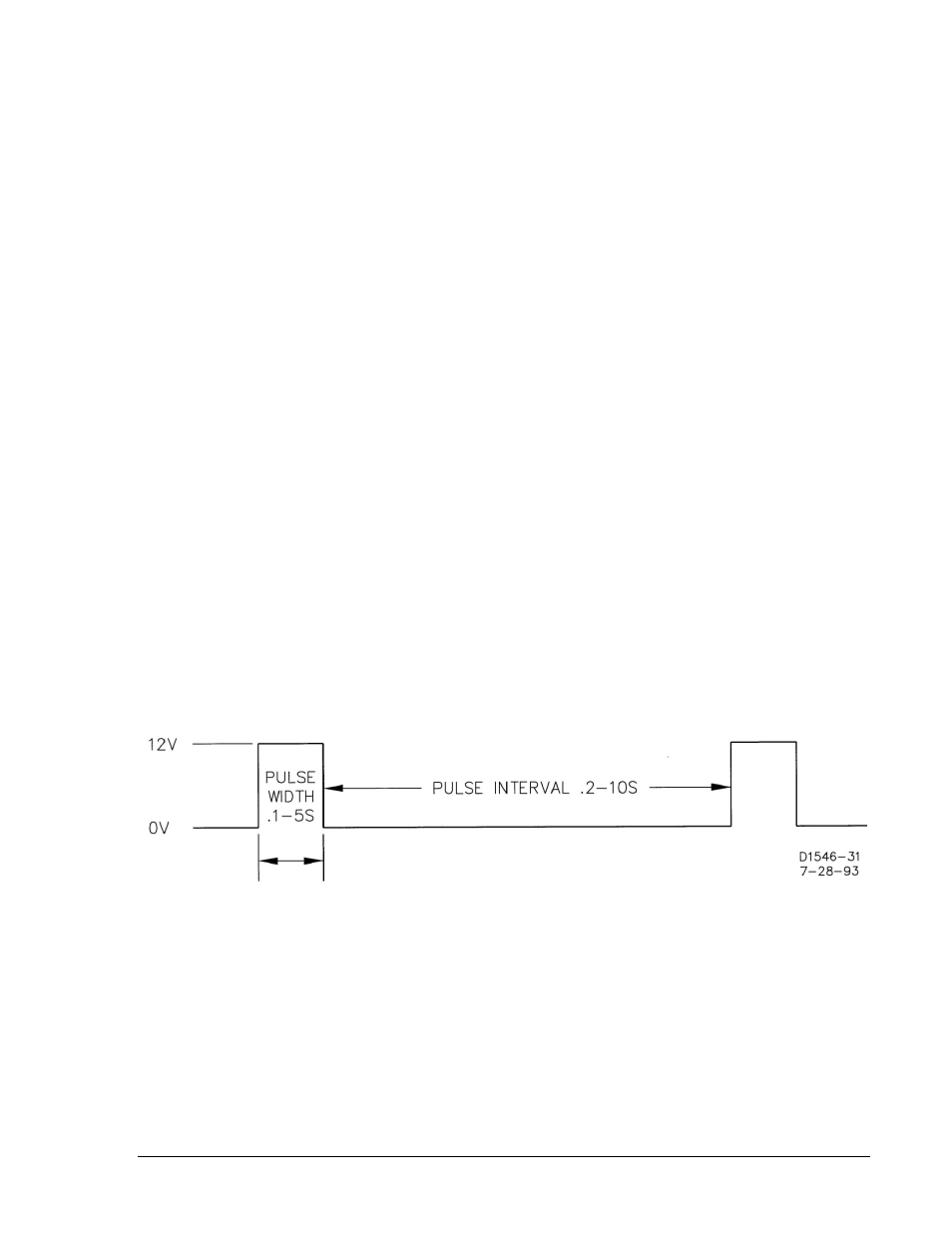
Step 3. Connect an oscilloscope or frequency counter to the jacks on the front panel of the V2 module.
Observe the following waveform (Figure 5-3).
Figure 5-3. Option V2 Waveform
Step 4. Adjust the PULSE WIDTH control for the desired pulse width. The LOWER LED should be ON
for the duration of the pulse width.
Step 5. Adjust the PULSE INTERVAL control for the desired interval. The LED should NOT be ON
during the interval.
Step 6. Set the simulated generator voltage to a value that is lower than the bus by an amount that
exceeds the Option A VOLTAGE DIFFERENCE control setting. The RAISE LED should be ON
for the duration of the pulse width.
Voltage Matching Module V3 Verification Test
An A1 or A2 module must be installed to enable this option. Use average-reading voltmeters scaled in
RMS.
9146600990 Rev S
BE1-25A Testing
5-11