Voltage matching module v3, Voltage matching module v3 -11 – Basler Electric BE1-25A User Manual
Page 31
Voltage Matching Module V3
Option V3 (Figure 2-12) is similar to Option V2, in that it initiates
corrective pulses that are used to increase or decrease the
generator voltage to within the voltage difference limit as
determined by the Voltage Acceptance module (either A1 or A2).
Both V2 and V3 are functionally identical when the voltage
difference between generator and bus is equal to or greater than
20.0 Vac.
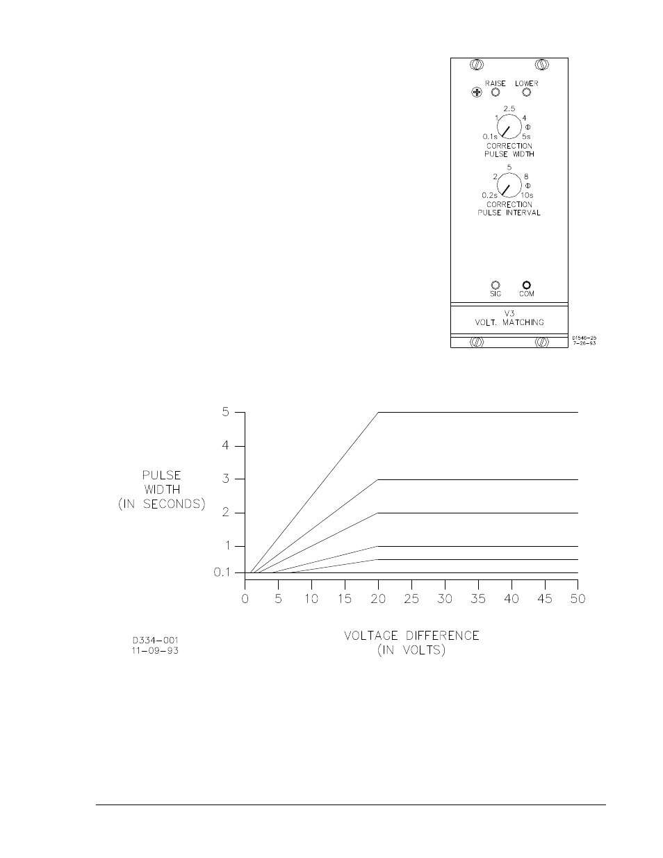
But when the voltage difference is less than 20.0 Vac, Option V3
differs in this respect: the duration of the corrective pulses no
longer follows in lockstep with the setting of the CORRECTION
PULSE WIDTH control. Instead, the duration of the corrective
pulses is reduced by an amount proportional to the correction
required (Figure 2-13). Note that the minimum pulse duration is
0.1 seconds.
The CORRECTION PULSE INTERVAL control determines the
period of the pulse train. (Unlike the PULSE WIDTH control, the
INTERVAL control does NOT vary from the setting as a function
of voltage difference.)
The pulses issued by this option (to direct either the raise or the
lower output relay) may be monitored at the SIG and COM jacks.
(+12 Vdc = relay de-energized; 0 Vdc = relay energized.)
Figure 2-12. Module V3
Figure 2-13. Pulse Duration Timing for Option V3
9146600990 Rev S
BE1-25A Human-Machine Interface
2-11