Ethernet termination and grounding recommendation – BECKHOFF EtherCAT Technology Section I User Manual
Page 51
Ethernet Physical Layer
Slave Controller
– Technology
I-31
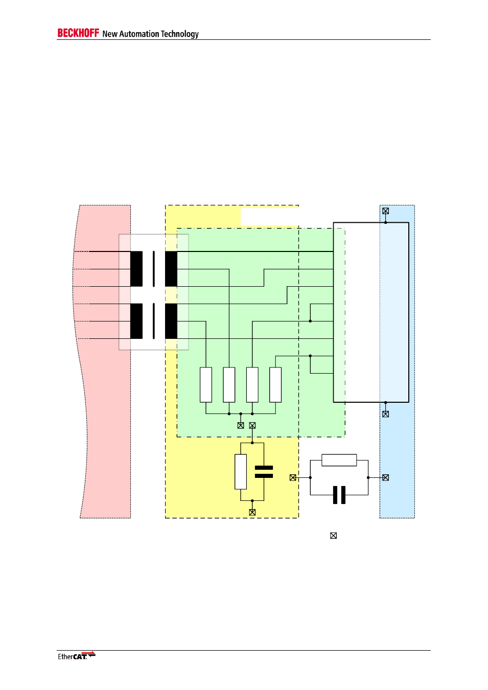
5.12 Ethernet Termination and Grounding Recommendation
This termination and grounding design recommendation may help to meet the overall requirements for
industrial communication. Nevertheless, implementation may vary depending on other requirements
like board layout, other capacities, common ground interconnection, and shield grounding.
Unused RJ-45 pins are terminated by 75
Ω resistors which will be connected to virtual ground. Virtual
GND is connected to Protection Earth (PE) by a 10nF/500V capacitor in parallel to a 1M
Ω resistor.
Shield is also connected to PE by a 10nF/500V capacitor in parallel to a 1M
Ω resistor. Especially the
values for the connection between Virtual GND and PE are subject to change to meet industrial
requirements (EMC). Shield is not directly connected with PE to avoid ground loops across large
industrial plants with different PE potentials.
This design recommendation of termination and grounding is shown in Figure 11.
Protection
Earth (PE)
Virtual Ground
Protection
Earth (PE)
Magnetics
Shield
RJ-45
2
3
4
5
6
7
8
9
10
1
1 M
1
M
1
0
n
F
/5
0
0
V
10 nF/500 V
> 2mm
gap
> 1mm gap between
PE and Virtual Ground
> 1mm
gap
plane connection
7
5
R
7
5
R
7
5
R
7
5
R
TX+
TX-
RX+
RX-
System
Ground
Figure 11: Termination and Grounding Recommendation