4 standard ebus link detection, 5 enhanced ebus link detection, Standard ebus link detection – BECKHOFF EtherCAT Technology Section I User Manual
Page 57: Enhanced ebus link detection, Figure 18: example ethercat network
EBUS/LVDS Physical Layer
Slave Controller
– Technology
I-37
6.4
Standard EBUS Link Detection
Standard EBUS link detection is realized by counting the number of good signal events (no RX error)
in a defined interval of time and comparing it to a given value. The link is established if enough events
occurred, and disconnected if too few events occurred. IDLE symbols as well as any kind of EtherCAT
traffic produce enough good events.
In order to handle partial link failures correctly, the following mechanism is used:
An ESC transmits at port 0 only if a link is detected (e.g., IDLE symbols are received), otherwise it
will transmit N- symbols.
An ESC transmits at ports 1, 2, and 3 regardless of the link state (typically IDLE symbols if no
frames are pending).
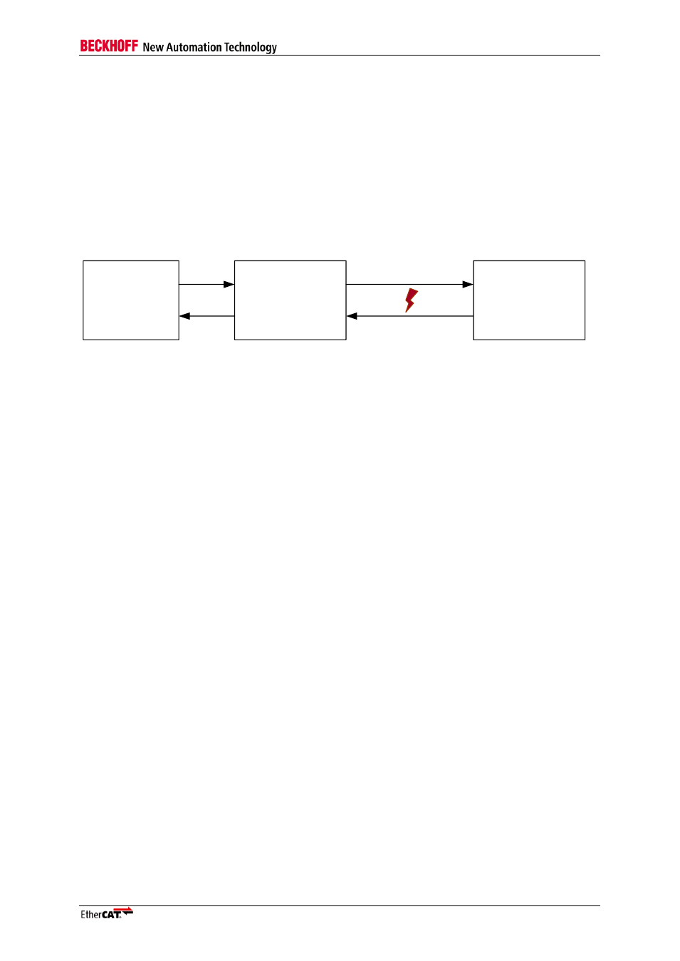
EtherCAT
master
EtherCAT
slave 1
Link A
Link B
P
o
rt
0
P
o
rt
1
EtherCAT
slave 2
P
o
rt
0
P
o
rt
1
Figure 18: Example EtherCAT Network
This method addresses these two cases of partial link failure (see Figure 18):
A failure on Link A will be detected by Slave 2, which will stop transmitting anything on Link B (and
close the loop at port 0). This is detected by Slave 1, which will close the loop at port 1. The
master can still communicate with slave 1.
A failure on Link B will be detected by Slave 1, which will close the loop at port 1. The master can
still communicate with slave 1. This failure cannot be detected by slave 2, which will leave port 0
open.
Do not connect any EBUS port 0 to another EBUS port 0 (same ESC or different ESCs) using
standard link detection, because standard link detection will not establish a link after it was down.
Do not connect any EBUS port 1-3 to another EBUS port 1-3 (same ESC or different ESCs) using
standard link detection, because partial link failures will not result in closed ports.
NOTE: Standard link detection cannot cope with a specific partial link fault (Link B failure), which affects
redundancy operation (e.g., port 1 of slave 2 is connected to the master), because the master cannot
communicate with slave 2 which leaves its port 0 open.
NOTE: Another advantage of this mechanism is that in case slave 2 is added to the network, at first port 0 of
slave 2 is opened because there is activity on Link A, then transmission on Link B is started, and finally slave 1
opens Port 1. This assures that no frames get lost during link establishment.
6.5
Enhanced EBUS Link Detection
Enhanced EBUS link detection uses the standard link detection mechanism and adds a simple link
detection handshake protocol before the link is established.
With enhanced link detection, the ESC transmits on all ports regardless of the link state (unless
frames are transmitted; typically IDLE symbols are transmitted if no frames are pending).
The handshake protocol consists of three phases:
1. Each device starts transmitting a 4 nibble link request frame with 0x55C4 regularly at each port.
This frame has no SOF/CRC and would be discarded if it was accidentally received by standard
Ethernet devices (e.g., masters).
2. If a link request frame (0x55C4) is received at a port, the ESC will transmit link acknowledge
frames (0x55CC) instead of link request frames at this port.
3. If a link acknowledge frame (0x55CC) is received at a port, the link at the port is established. Both
link partners know that the link is good and establish the link. No further link detection frames are
transmitted (until the link is interrupted and the link detection handshake phases are starting from
the beginning).