3 pdi register function acknowledge by write, Pdi register function acknowledge by write, Table 24: ethercat mailbox header – BECKHOFF EtherCAT Technology Section I User Manual
Page 64: Figure 25: ethercat mailbox header (for all types), Prio, Type, Channe
SyncManager
I-44
Slave Controller
– Technology
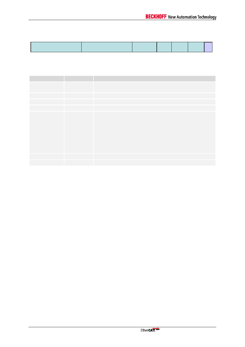
The content of an EtherCAT mailbox header is shown in Figure 25.
Figure 25: EtherCAT Mailbox Header (for all Types)
Table 24: EtherCAT Mailbox Header
Field
Data Type
Value/Description
Length
WORD
Number of Bytes of this mailbox command excluding the mailbox
header
Address
WORD
Station Address of originator
Channel
6 bit
0
– reserved for future use
Priority
2 bit
Priority between 0 (lowest) and 3 (highest)
Type
4 bit
Mailbox protocol types:
0x0: Error
0x1: Vendor specific (Beckhoff: AoE
– ADS over EtherCAT)
0x2: EoE (Ethernet over EtherCAT)
0x3: CoE (CAN application layer over EtherCAT)
0x4: FoE (File access over EtherCAT)
0x5: SoE (Servo profile over EtherCAT)
0xF: Vendor specific (VoE)
Ctr.
3 bit
Sequence number that is used for detection of duplicated frames
Reserved
1 bit
0
8.3
PDI register function acknowledge by Write
Refer to chapter 16.2 for the background of this function, which only affects the SyncManager
operation when the PDI reads a buffer. The EtherCAT operation is not influenced by this optional
feature.
Reading a SyncManager buffer consists of the following steps, if PDI register function acknowledge by
Write is enabled:
Read the first byte.
This will open the buffer. Accidentally reading subsequent bytes has no influence.
Read any byte of the buffer.
This includes the first byte, the last byte, and any inner byte. The buffer remains open, and the
buffer can even be read multiple times. Accidentally reading the last byte has no influence.
Write to the last byte of the buffer.
Byte enable signals are used, write data is ignored (write 0). This write operation closes the buffer.
Accidentally reading the first byte of a second SyncManager buffer behind the one to be read is still
possible, this will open the second SyncManager buffer. This can easily be prevented by aligning
SyncManager buffer start addresses to the data width of the µController. It is recommended to align
SyncManager buffer start addresses to 64 bit (8 byte) boundaries anyway.
8.4
Interrupt and Watchdog Trigger Generation, Latch Event Generation
Interrupts can be generated when a buffer was completely and successfully written or read. A
watchdog trigger signal can be generated to rewind (trigger) the Process Data watchdog used for
Digital I/O after a buffer was completely and successfully written. Interrupt and watchdog trigger
generation are configurable. The SyncManager Status register reflects the current buffer state.
For debugging purposes it is also possible to trigger Distributed Clock Latch events upon successful
buffer accesses (for some ESCs).
Ctr.
Type
Prio
Channe
l
Address
Length
16 Bit
16 Bit
6 Bit
2 Bit 4 Bit 3 Bit 1 Bit
0
16
32
38
40
44
0
.
47