5 sync1 generation, Figure 31: sync0/1 cycle time examples – BECKHOFF EtherCAT Technology Section I User Manual
Page 83
Distributed Clocks
Slave Controller
– Technology
I-63
9.2.3.5
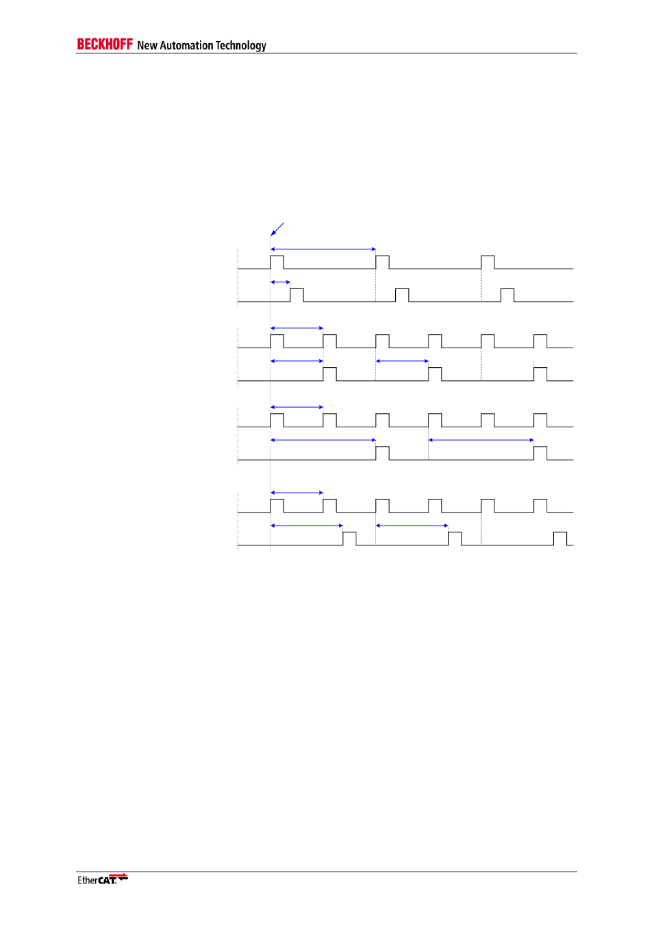
SYNC1 Generation
The second SyncSignal (SYNC1) depends on SYNC0, it can be generated with a predefined delay
after SYNC0 pulses. The delay is configured in the SYNC1 Cycle Time register (0x09A4:0x09A7).
If the SYNC1 Cycle Time is larger than the SYNC0 Cycle Time, it will be generated as follows: when
the Start Time Cyclic Operation is reached, a SYNC0 pulse is generated. The SYNC1 pulse is
generated after the SYNC0 pulse with a delay of SYNC1 Cycle Time. The next SYNC1 pulse is
generated when the next SYNC0 pulse was generated, plus the SYNC1 Cycle Time.
Some example configurations are shown in the following figure:
SYNC0
SYNC1
SYNC1 Cycle Time
SYNC0 Cycle Time
SYNC0
SYNC1
SYNC1 Cycle Time
SYNC0 Cycle Time
SYNC1 Cycle Time < SYNC0 Cycle Time
SYNC1 Cycle Time = SYNC0 Cycle Time
SYNC0
SYNC1
SYNC1 Cycle Time
SYNC0 Cycle Time
SYNC1 Cycle Time = 2*SYNC0 Cycle Time
SYNC1 Cycle Time
SYNC1 Cycle Time
SYNC0
SYNC1
SYNC1 Cycle Time
SYNC0 Cycle Time
SYNC1 Cycle Time > SYNC0 Cycle Time
and
SYNC1 Cycle Time < 2*SYNC0 Cycle Time
SYNC1 Cycle Time
Start Time
Figure 31: SYNC0/1 Cycle Time Examples
NOTE: If The SYNC1 Cycle Time is 0, SYNC1 reflects SYNC0.