6 ebus rx errors, 7 ebus low jitter, 8 ebus connection – BECKHOFF EtherCAT Technology Section I User Manual
Page 58: Ebus rx errors, Ebus low jitter, Ebus connection, Figure 19: ebus connection, Ethercat device
EBUS/LVDS Physical Layer
I-38
Slave Controller
– Technology
Link disconnection is signaled to the link partner by stopping transmission for a certain time. This will
be detected by the default link detection mechanism. The link gets disconnected at both sides, and
both sides close their loops. After that, the first phase of the handshake protocol starts again.
EBUS enhanced link detection is not compatible with older devices which forward enhanced link
detection handshake frames depending on the direction (e.g. ESC20 and bus terminals without
ASICs): the handshake frames are not forwarded through the EtherCAT Processing Unit, but they are
forwarded without modification alongside the EtherCAT Processing Unit.
A device using enhanced link detection will stop generating handshake frames after the link is
established or the enhanced link detection is disabled by SII EEPROM setting. It will restart generating
handshake frames shortly after a link is lost (unless enhanced link detection is disabled).
6.6
EBUS RX Errors
The EBUS receiver detects the following RX errors:
Missing edge in the middle of one bit (but not EBUS SOF/EOF)
EBUS SOF inside a frame (two SOFs without EOF in between)
EBUS EOF outside a frame (two EOFs without SOF in between)
IDLE violation: ‘1’ outside a frame
Too short pulses (less than ~3.5 ns)
A frame with an RX error is discarded. Too many RX errors in a defined interval of time will result in
link disconnection.
Errors outside of a frame are counted only once, and errors inside a frame are also counted only once,
because the Manchester decoding might have lost synchronization.
6.7
EBUS Low Jitter
In Low Jitter mode, the jitter of the forwarding delay (EBUS port to EBUS port) is reduced.
6.8
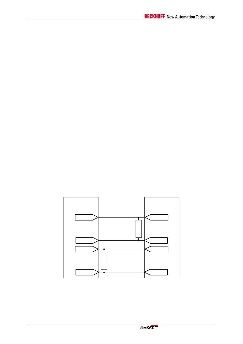
EBUS Connection
The connection of two EBUS ports is shown in Figure 19. LVDS termination with 100 Ohm impedance
is necessary between each pair of receive signals
– located adjacent to the receive inputs.
EtherCAT
device
TX+
TX-
RX+
RX-
1
0
0
R
1
0
0
R
EtherCAT
device
RX+
RX-
TX+
TX-
Figure 19: EBUS Connection