Figure 21: fmmu mapping example – BECKHOFF EtherCAT Technology Section I User Manual
Page 60
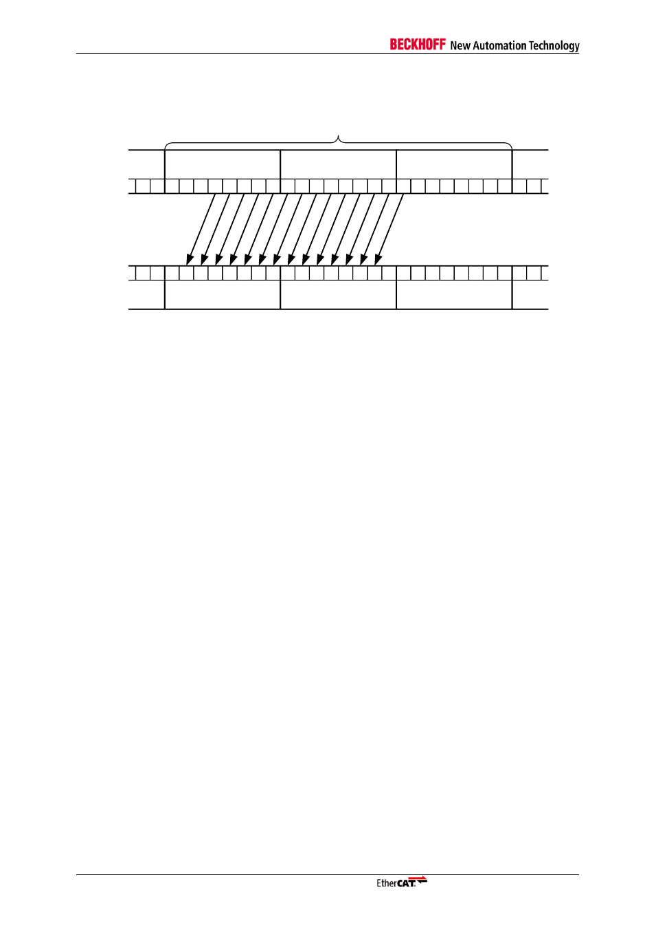
FMMU
I-40
Slave Controller
– Technology
0
7
6
5
4
3
2
1
0
7
6
5
4
3
2
1
0
7
6
5
4
3
2
1
0
7
6
Byte 0x00010011
Logical Start Address
1
0
7
6
5
4
3
2
1
0
7
6
5
4
3
2
1
0
7
6
5
4
3
2
1
0
7
6
1
Byte 0x00010012
Byte 0x00010013
Byte 0x0F02
Byte 0x0F02
Byte 0x0F01
Physical Start Address
Logical Address Space
Physical Address Space
Logical Start bit = 3
Logical Stop Bit = 0
Physical Start bit = 1
Configured FMMU Length = 3 Bytes
14 Bits mapped
Figure 21: FMMU Mapping Example
Attention: This drawing of the bit string shows the least significant bit first, in a hexadecimal representation of the
octets the least significant value is at the right place and the most significant on the left place (00110011 is
represented as octet by 0xCC).
Restrictions on FMMU Settings
The FMMUs of Beckhoff ESCs are subject to restrictions. The logical address ranges of two FMMUs
of the same direction (read or write) in one ESC must be separated by at least 3 logical bytes not
configured by any FMMU of the same type, if one of the FMMUs or both use bit-wise mapping (logical
start bit
≠ 0, logical stop bit ≠ 7, or physical start bit ≠ 0). In the above example, the first logical address
area after the one shown must have a logical start address of 0x00010017 or higher (the last byte of
the example FMMU is 0x00010013, three bytes free 0x00010014-0x00010016).
If only byte-wise mapping is used (logical start bit = 0, logical stop bit = 7, or physical start bit = 0), the
logical address ranges can be adjacent.
Bit-wise writing is only supported by the Digital Output register (0x0F00:0x0F03). All other registers
and memories are always written byte-wise. If bit-wise mapping is used for writing into these areas,
bits without mapping to logical addresses are written with undefined values (e.g., if only physical
address bit 0x1000[0] is mapped by a write FMMU, the bits 1-7 are written with undefined values).
Additional FMMU Characteristics
Each logical address byte can at most be mapped either by one FMMU(read) plus one
FMMU(write), or by one FMMU(read/write). If two or more FMMUs (with the same direction
– read
or write) are configured for the same logical byte, the FMMU with the lower number (lower
configuration address space) is used, the other ones are ignored.
One or more FMMUs may point to the same physical memory, all of them are used. Collisions
cannot occur.
It is the same to use one read/write FMMU or two FMMUs
– one read, the other one write – for the
same logical address.
A read/write FMMU cannot be used together with SyncManagers, since independent read and
write SyncManagers cannot be configured to use the same (or overlapping) physical address
range.
Bit-wise reading is supported at any address. Bits which are not mapped to logical addresses are
not changed in the EtherCAT datagram. E.g., this allows for mapping bits from several ESCs into
the same logical byte.
Reading an unconfigured logical address space will not change the data.