Transducer connection diagrams, I.4 electrical installation – Yaskawa iQpump Micro Quick Start User Manual
Page 45
u
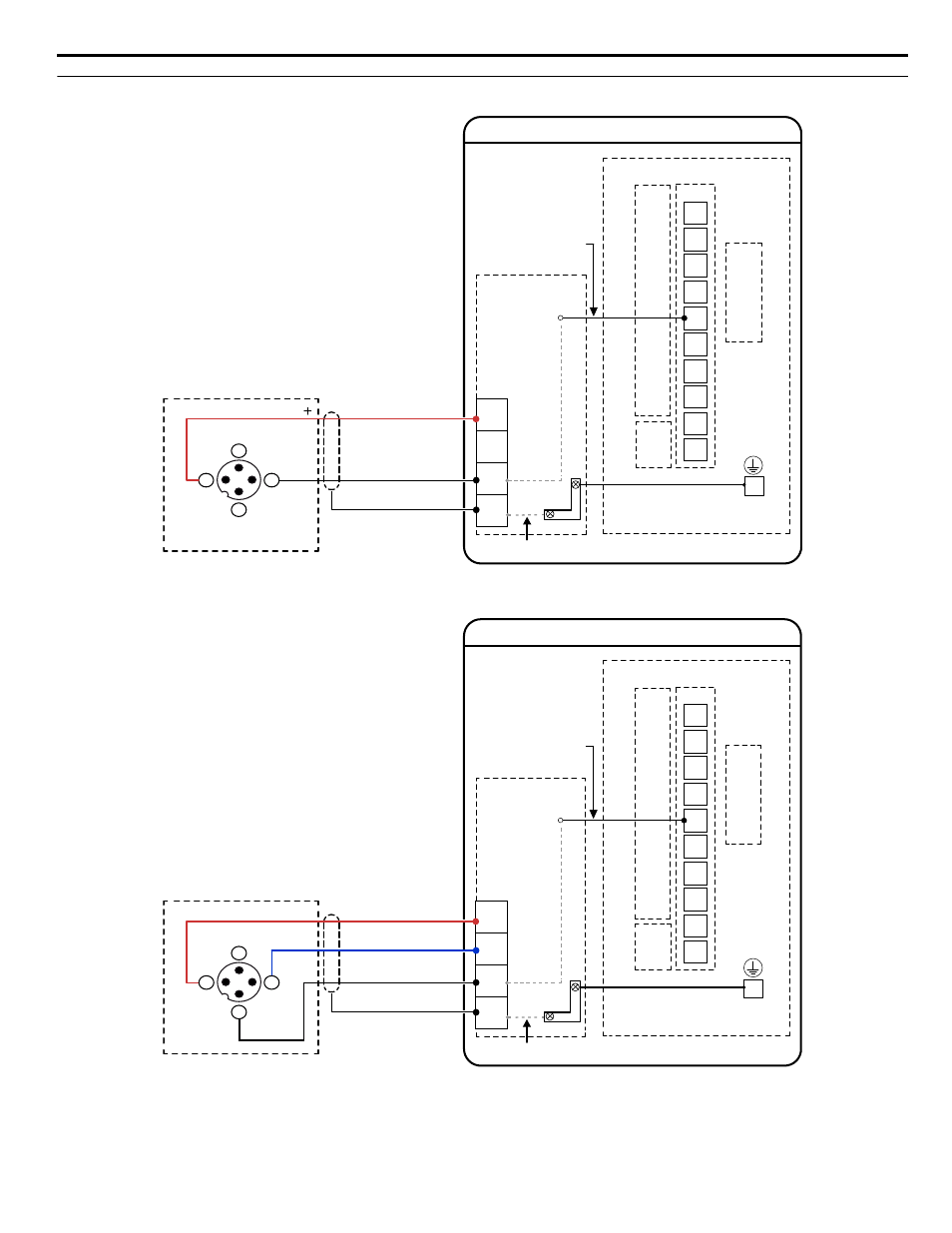
Transducer Connection Diagrams
Signal Wire (white)
24 V PSU to Drive
A2
24V
AC
FE
24V Power Supply
Shield
SIG
FE
Functional Earth Cable
(Blue)
J2
24V Power Supply
Transducer
Signal 4-20 mA
(typical)
CN1
Terminal
Block
TB1-2
TB1-1
TB2
TB1-3
EG
A2
A1
PC
P2
V+
AM
AC
MP
AC
P1
iQpump Micro Drive
(Earth
Ground)
Internal Circuit
Internal Circuit
iQpump Micro Drive
I/O Terminals
2
4
3
1
N/C
N/C
V+
Output
Example:
Customer supplied
pressure transducer
feedback device
(2-Wire)
Figure i.11 Transducer 2-Wire Connection Diagram
Signal Wire (white)
24 V PSU to Drive
A2
24V
AC
FE
24V Power Supply
Shield
FE
Functional Earth Cable
(Blue)
J2
24V Power Supply
Transducer
Signal 0-10 Vdc
(typical)
CN1
Terminal
Block
Example:
Customer supplied
pressure transducer
feedback device
(3-Wire)
TB1-2
TB1-1
TB2
TB1-3
EG
A2
A1
PC
P2
V+
AM
AC
MP
AC
P1
iQpump Micro Drive
(Earth
Ground)
Internal Circuit
Internal Circuit
iQpump Micro Drive
I/O Terminals
Supply Common
2
4
3
1
N/C
V+
Output
Com
+
Figure i.12 Transducer 3-Wire Connection Diagram
i.4 Electrical Installation
YASKAWA TOEP YAIQPM 02B YASKAWA AC Drive - iQpump Micro Quick Start Guide
45