Sinking/sourcing mode switch, Transistor input signal using 0 v common/sink mode, I.5 main circuit wiring – Yaskawa iQpump Micro Quick Start User Manual
Page 54
u
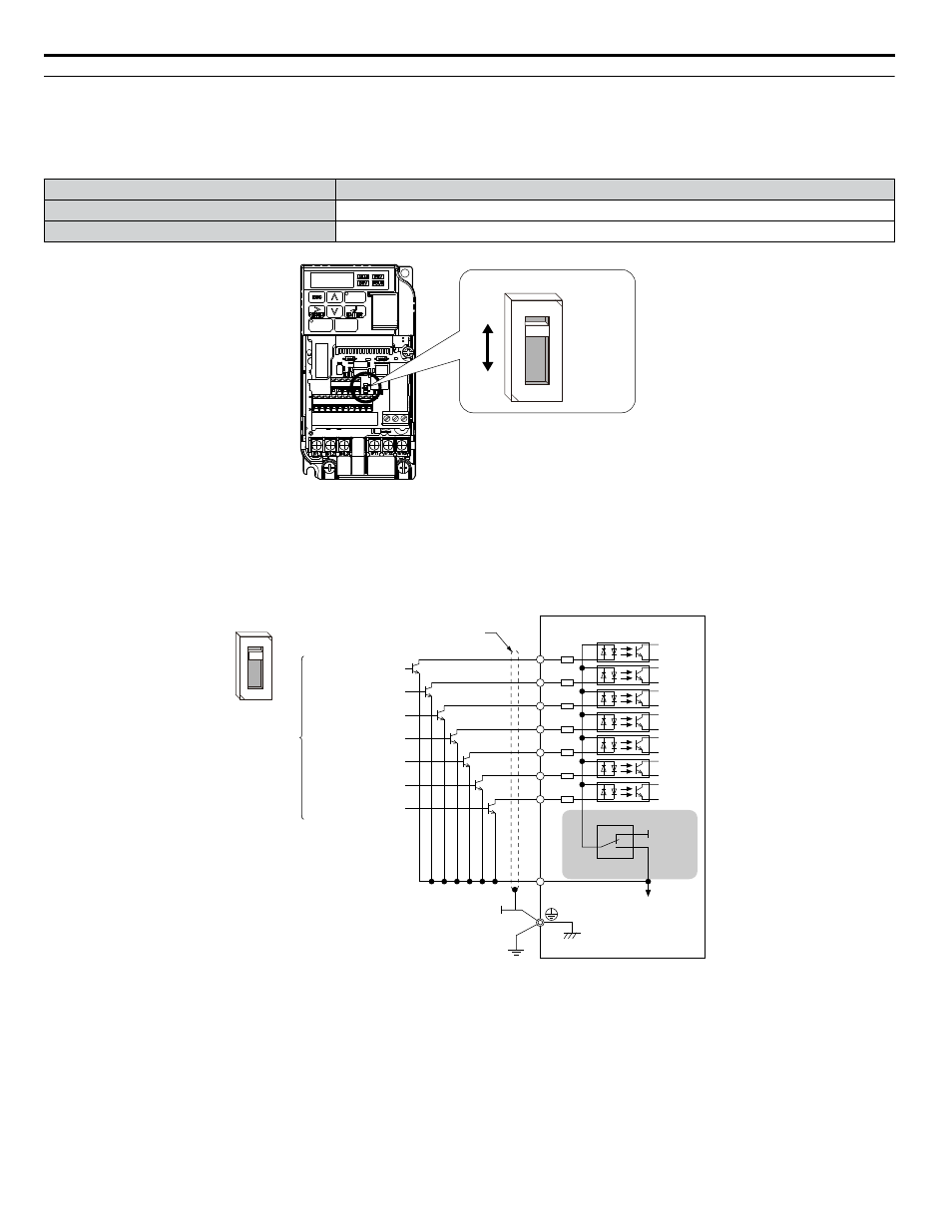
Sinking/Sourcing Mode Switch
Set the DIP switch S3 on the front of the drive to switch the digital input terminal logic between sinking mode and sourcing
mode; the drive is preset to sinking mode.
Table i.12 Sinking/Sourcing Mode Setting
Set Value
Details
SINK
Sinking Mode (0 V common): default setting
SOURCE
Sourcing Mode (+24 V common)
DIP Switch S3
SINK
SOURCE
Figure i.20 DIP Switch S3
n
Transistor Input Signal Using 0 V Common/Sink Mode
When controlling the digital inputs by NPN transistors (0 V common/sinking mode), set the DIP switch S3 to SINK and use
the internal 24 V power supply.
Drive
Shielded cable
Forward run/stop
Reverse run/stop
External fault N.O.
Fault reset
Multi-speed step 1
Multi-speed step 2
Jog reference
Multi-function input
S1
S2
S3
S3
+24V
S4
S5
S6
S7
SC
SINK
SOURCE
SINK
SOURCE
Figure i.21 Sinking Mode: Sequence from NPN Transistor (0 V Common)
i.5 Main Circuit Wiring
54
YASKAWA TOEP YAIQPM 02B YASKAWA AC Drive - iQpump Micro Quick Start Guide