Drive specifications, I.8 drive specifications – Yaskawa iQpump Micro Quick Start User Manual
Page 87
i.8
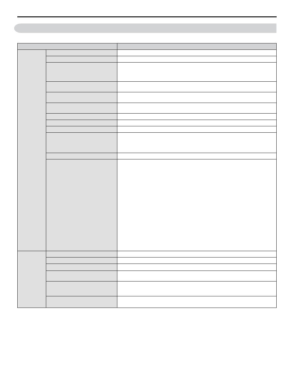
Drive Specifications
Note:
For optimum performance life of the drive, install the drive in an environment that meets the required specifications.
Item
Specification
Control
Character-
istics
Control Method
V/f Control (V/f)
Frequency Control Range
0.01 to 400 Hz
Frequency Accuracy
Digital input: within ±0.01% of the max output frequency
(-10 to +50 °C)
Analog input: within ±0.5% of the max output frequency
(25 °C ±10 °C)
Frequency Setting Resolution
Digital inputs: 0.01 Hz
Analog inputs: 1/1000 of maximum output frequency
Output Frequency Calculation
Resolution
1/2
20
x Maximum output frequency (E1-04)
Frequency Setting Signal
Main frequency reference: 0 to +10 Vdc (20 kΩ), 4 to 20 mA (250 Ω), 0 to 20 mA (250 Ω)
Main speed reference: Pulse Train Input (max 32 kHz)
Starting Torque
V/f: 150% at 3 Hz
Speed Control Range
1:40 (V/f Control)
Accel/Decel Time
0.00 to 6000.0 s (allows four separate settings for accel and decel)
Braking Torque
Instantaneous Average Decel Torque
<1>
: 0.1/0.2 kW: over 150%, 0.4/0.75 kW: over 100%,
1.5 kW: over 50%, 2.2 kW and above: over 20%
Continuous Regen Torque: 20%,
125% with a Braking Resistor Unit
<2>
: (10% ED) 10 s with an internal braking resistor.
V/f Characteristics
Preset V/f patterns and user-set program available.
Functions
Momentary Power Loss Ride-Thru
Speed Search
Over/Undertorque Detection
Multi-Step Speed (17 steps max)
Accel/Decel Time Switch
S-Curve Accel/Decel,
2-Wire/3-Wire Sequence
Stationary Auto-Tuning of Line-to-Line Resistance
Dwell
Cooling Fan ON/OFF
Slip Compensation
Torque Compensation
Jump Frequencies (reference dead band)
Frequency Reference Upper/Lower Limit
DC Injection Braking (start and stop)
PID Control (with Sleep Function)
MEMOBUS/Modbus (RS-485/RS-422 Max 115.2 kbps)
Fault Reset
Parameter Copy
Fault Restart
Removable Terminals with Parameter Backup Function
Protection
Functions
Motor Protection
Motor overheat protection via output current sensor
Overcurrent Protection
Drives stops when output exceeds 170% of the rated current
Overload Protection
Drive stops when output current is 120% rated current for 60 sec.
<3>
Overvoltage Specification
200 V Class: Stops when DC bus voltage exceeds approx. 410 V
400 V Class: Stops when DC bus voltage exceeds approx. 820 V
Low Voltage Protection
Drive stops when DC bus voltage falls below the levels indicated:
190 V (3-phase 200 V), 160 V (single-phase 200 V), 380 V (3-phase 400 V), 350 V (3-phase
380 V)
Momentary Power Loss Ride-Thru
3 selections available: Ride-Thru disabled (stops after 15 ms), time base of 0.5 s, and continue
running as long as the drive control board is powered up.
<4>
i.8 Drive Specifications
YASKAWA TOEP YAIQPM 02B YASKAWA AC Drive - iQpump Micro Quick Start Guide
87