Yaskawa iQpump Micro Quick Start User Manual
Page 68
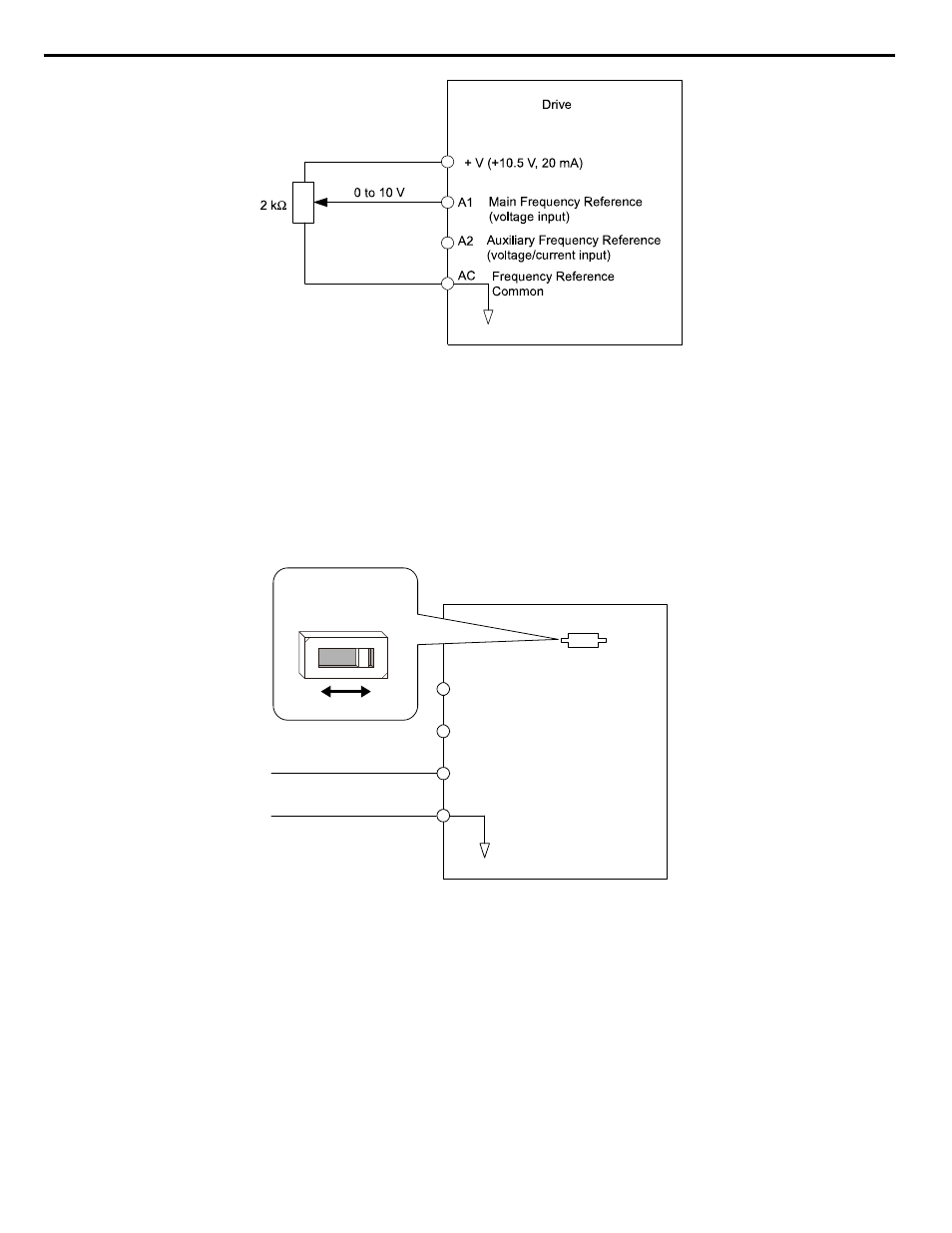
Figure i.30 Setting the Frequency Reference by Voltage Input
• Using Control Circuit Terminal A2 (0 to 10 Vdc voltage input)
Use the same connection as explained for terminal A1 for terminal A2. Make sure that switch S1 is set to “V” and set the
appropriate signal level for terminal A2 by entering 0 or 1 into parameter H3-09. The terminal A2 function must be set to
frequency bias by entering 0 into parameter H3-10.
• Using Control Circuit Terminal A2 (0/4 to 20 mA current input)
Connect input A2 to an external current source such as the one shown in
. Make sure that switch S1 is set to “I”
and set the appropriate signal level for terminal A2 by entering 2 (4 to 20 mA) or 3 (0 to 20 mA) into parameter H3-09. The
terminal A2 function must be set to frequency bias by entering 0 into parameter H3-10.
Drive
A1
A2
Frequency reference
Frequency reference bias
AC
Analog common
+V (+10.5 V, 20 mA power supply)
0 or 4 to 20 mA input
DIP switch S1
V
I
Figure i.31 Setting the Frequency Reference by Current Input
Switching between Main/Auxiliary Frequency References
The frequency reference input can be switched between terminal A1 (main) and terminal A2 (auxiliary). When using this
function:
• Make sure that b1-01 is set to “1” (Frequency reference from analog input).
• Set the terminal A2 function to auxiliary frequency (H3-10 = 2).
• Set one digital input to multi-speed 1 (H1-oo = 3, default for S5).
The frequency reference value is read from
• Terminal A1 when the digital input set for multi-speed 1 is open.
• Terminal A2 when the digital input set for multi-speed 1 is closed.
shows a wiring example for main/auxiliary reference switching using digital input S5.
i.6 Start-Up Programming and Operation
68
YASKAWA TOEP YAIQPM 02B YASKAWA AC Drive - iQpump Micro Quick Start Guide