Wiring checklist – Yaskawa iQpump Micro Quick Start User Manual
Page 56
V
I
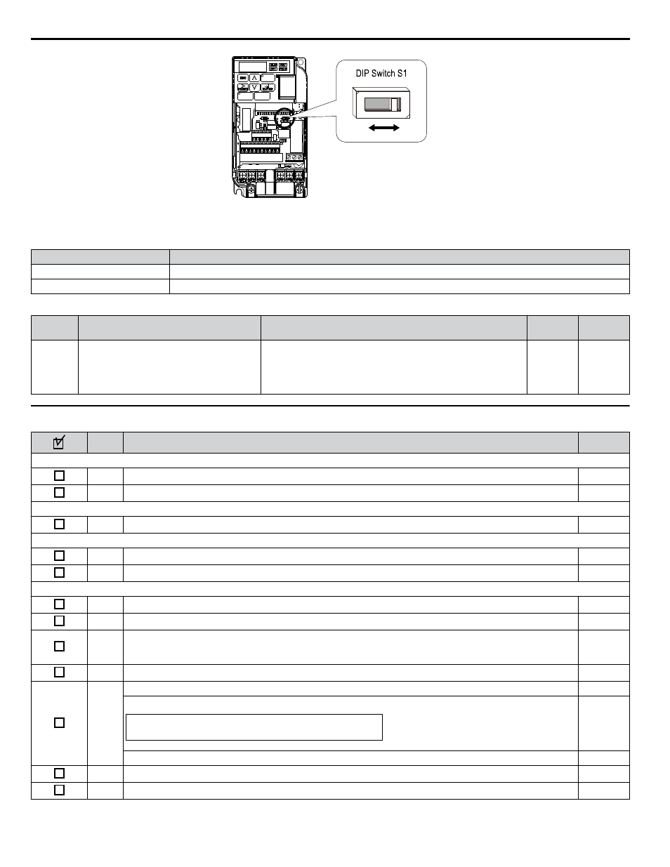
Figure i.23 DIP Switch S1
Table i.14 DIP Switch S1 Settings
Setting Value
Description
V (eft position)
Voltage input (0 to 10 V)
I (right position)
Current input (4 to 20 mA or 0 to 20 mA): default setting
Table i.15 Parameter H3-09 Details
No.
Parameter Name
Description
Setting
Range
Default
Setting
H3-09
Frequency ref. (current)
terminal A2 signal level selection
Selects the signal level for terminal A2.
0: 0 to +10 V, unipolar input (with lower limit)
1: 0 to +10 V, bipolar input (no lower limit)
2: 4 to 20 mA
3: 0 to 20 mA
0 to 3
2
u
Wiring Checklist
No.
Item
Page
Drive, peripherals, option cards
1
Check drive model number to ensure receipt of correct model.
2
Check for correct braking resistors, DC link chokes, noise filters, and other peripheral devices.
–
Installation area and physical setup
3
Ensure area surrounding the drive complies with specifications.
Power supply voltage, output voltage
4
The voltage from the power supply should fall within the input voltage specification range of the drive.
–
5
The voltage rating for the motor should match the drive output specifications.
Main circuit wiring
6
Confirm proper branch circuit protection exists per National and Local codes.
7
Properly wire the power supply to drive terminals R/L1, S/L2 and T/L3.
–
8
Properly wire the drive and motor together.
The motor lines and drive output terminals R/T1, V/T2 and W/T3 should match in order to produce the desired
phase order. If the phase order is incorrect, the drive will rotate in the opposite direction.
9
Use 600 Vac vinyl-sheathed wire for the power supply and motor lines.
10
Use the correct wire gauges for the main circuit. Refer to
When using comparatively long motor cable, calculate the amount of voltage drop.
3 x voltage resistance (Ω/km) x cable length (m) x motor rated current (A) x 10
-3
Motor rated voltage (V) x 0.02 ≥
If the cable between the drive and motor exceeds 50 m, adjust the carrier frequency (C6-02) accordingly.
11
Properly ground the drive.
12
Tightly fasten all terminal screws. Refer to
, or
.
i.5 Main Circuit Wiring
56
YASKAWA TOEP YAIQPM 02B YASKAWA AC Drive - iQpump Micro Quick Start Guide