Yaskawa iQpump Micro Quick Start User Manual
Page 69
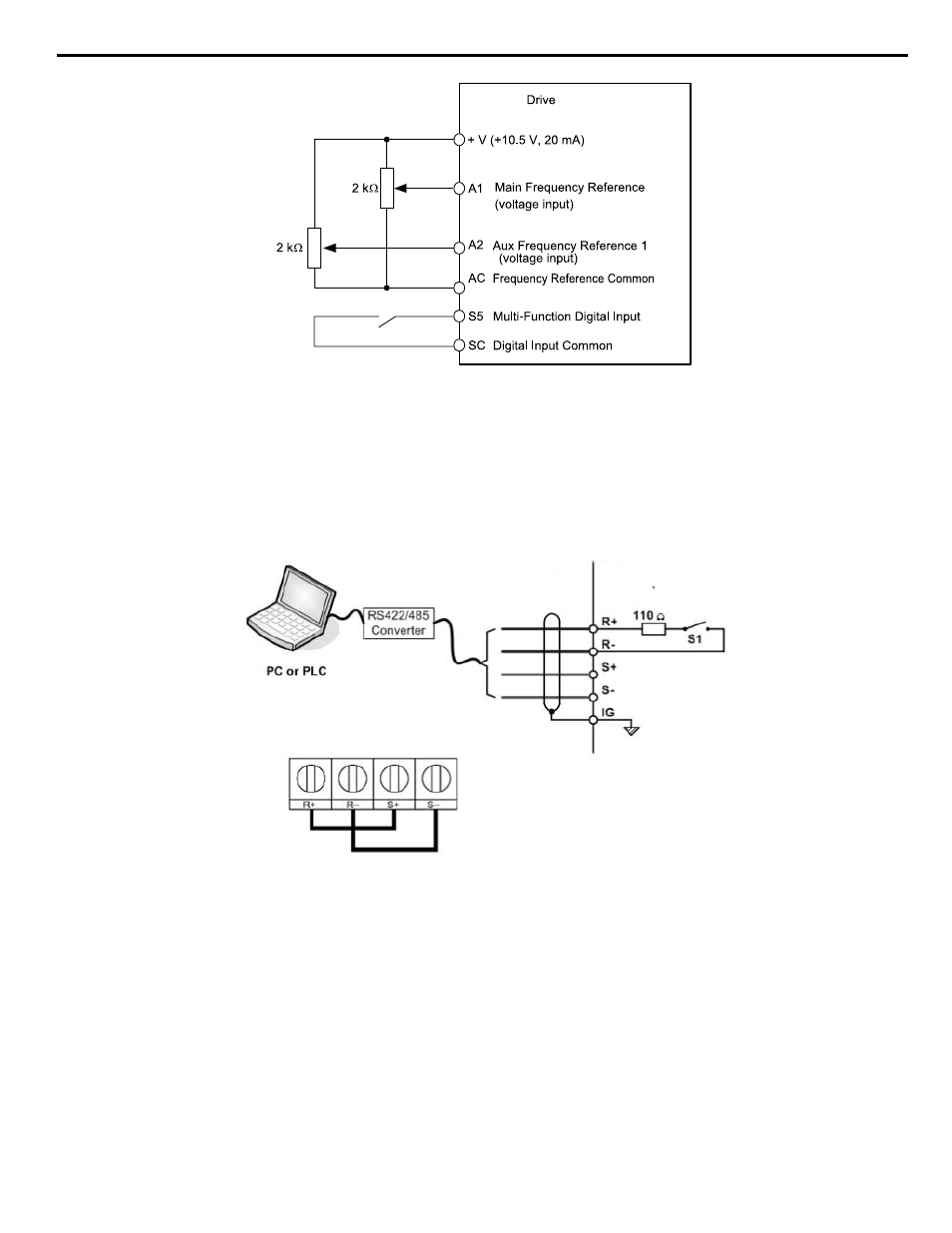
Figure i.32 Switching between Analog Reference 1 and 2
Setting 2: MEMOBUS/Modbus Communications
This setting requires entering the frequency reference via the RS-485/422 serial communications port (control terminals R+,
R-, S+, S-).
To setup the drive to receive the “Auto Setpoint” from serial communication, set b1-01 to “2: Serial Com,” and connect the
RS-422/RS-485 serial communications cable to terminals R+, R-, S+, and S- on the control I/O terminal block. Refer to
to see the connection diagram using a PC to provide the auto setpoint reference to the drive.
Figure 5.4
RS-485 Communication Connection
Modbus RTU Communications
RS-422/RS-485
19.2 Kbps
Terminating
Resistor
Figure i.33 PC or PLC Connection Diagram
Setting 3: Option card
This setting requires entering the frequency reference via an option board plugged into connector CN5 on the drive control
board. Consult the option board manual for instructions on integrating the drive with the communication system.
Note:
If the frequency reference source is set for Option PCB (b1-01 = 3), but an option board is not installed, an oPE05 Operator Programming
Error will be displayed on the digital operator and the drive will not run.
To setup the drive to receive the “Auto Setpoint” for a network communication option card, set b1-01 to “3: Option PCB”,
and plug a supported communication option card into the drive control PCB. Consult the manual supplied with the option for
instructions on integrating the drive into the network system.
Setting 4: Pulse Train Input
This setting requires a pulse train signal to terminal RP to provide the frequency reference. Follow the directions below to
verify that the pulse signal is working properly.
i.6 Start-Up Programming and Operation
YASKAWA TOEP YAIQPM 02B YASKAWA AC Drive - iQpump Micro Quick Start Guide
69